This image and associated text in the article is one thing that made a lot of sense, where "voltage drive" or "current drive" would be usefull:

Cone movement varies the Zi. Reduce effect of varying Zi by increasing external impedance in the circuit where Zi is significant. Zm in turn is the driver resonance which in turn would benefit minimal circuit impedance for electrical damping, reducing movement.
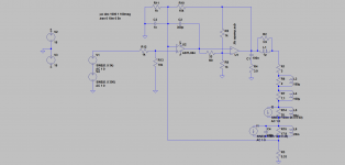
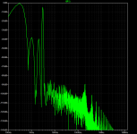
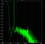
Some simulation again, this time with two disturbers (1kHz & 2kHz, each 100mA) within the load. Driving signal as before 300Hz & 3kHz
Attachment 1: showing where the disturbers are mounted
Attachment 2: simulation voltage driven
Attachment 3: simulation current driven
Attachment 4: simulation file
in this simulation i think the benefit of current drive is obvious
Attachment 1: showing where the disturbers are mounted
Attachment 2: simulation voltage driven
Attachment 3: simulation current driven
Attachment 4: simulation file
in this simulation i think the benefit of current drive is obvious
Attachments
-
 BE-composite-cdr-two disturbers within the load.png21.1 KB · Views: 97
 -
 spectrum_300Hz_3kHz_disturbed 1k-2k-100mA-voltage driven_blackman-harris filter.png22 KB · Views: 99
 -
 spectrum_300Hz_3kHz_disturbed 1k-2k-100mA-current driven_blackman-harris filter.png21.5 KB · Views: 94
 -
composite-amp_mit virtuellem power-op_current-drive-rlc-Last.asc4.6 KB · Views: 71
Have you validated the simulation model by measuring the distortion in reality? There're a lot of variables in SPICE simulations (step size, for example) that can throw off your THD results. Some opamp models don't have distortion included in the model. Etc., etc. I'm not saying this is the case for you – I have no insight into that – I'm just saying that it's something to be aware of with simulations of distortion.
Tom
Tom
The model for the power amp is a very simple one and i did not expect it to be perfectly exact. It is a little optimistic, but it comes close - at least in simulation for the voltage amplifier shown and a resistive load. The step size i use is very small (max. 5ns/step) - this lowers the "floor" .
I am aware that the picture simulation result shows can not exactly 1:1 be transferred to reality. But that was not the point here. I just wanted to figure out how current drive works. And now i think i got it. The "disturbers" that i modeled as current sources within the load have no effect on the signal curent when the load is current driven. Assuming it is the current that "transferes" the music i expect the resulting sound to be (at least a little) more transparent. I have to proof that on my system. The "disturbers" have not dissapeared, but now they "disturb" the voltage across the loads connectors.
I am aware that the picture simulation result shows can not exactly 1:1 be transferred to reality. But that was not the point here. I just wanted to figure out how current drive works. And now i think i got it. The "disturbers" that i modeled as current sources within the load have no effect on the signal curent when the load is current driven. Assuming it is the current that "transferes" the music i expect the resulting sound to be (at least a little) more transparent. I have to proof that on my system. The "disturbers" have not dissapeared, but now they "disturb" the voltage across the loads connectors.
Reading the linked article, I am finding myself asking, but "Is this not why many speaker cabinets/boxes have more than one driver?" Driver frequency matching is for better performance, in other words, to use specific drivers to cover smaller and dedicated portions of the audio spectrum.
Am I right? Is this not a solution to get better performance and still use the simpler voltage drive?
Am I right? Is this not a solution to get better performance and still use the simpler voltage drive?
yes, limit bandwidth per driver ") and bigger / more woofers to increase Sd, which reduces excursion for given volume displacement. And better drivers. Do all this, pay attention to crossover and there is not much current drive would make better. You could still use current drive if hou wanted.
and bigger / more woofers to increase Sd, which reduces excursion for given volume displacement. And better drivers. Do all this, pay attention to crossover and there is not much current drive would make better. You could still use current drive if hou wanted.
Basically its enough to get distortion inaudible, low enough. If its small speaker, then current drive might make audible difference. If its big speaker, passive crossover and good drivers then there would be less benefits going current drive, assuming livingroom use. As DIY we can do anything so, whatever rocks the boat.
and bigger / more woofers to increase Sd, which reduces excursion for given volume displacement. And better drivers. Do all this, pay attention to crossover and there is not much current drive would make better. You could still use current drive if hou wanted.Basically its enough to get distortion inaudible, low enough. If its small speaker, then current drive might make audible difference. If its big speaker, passive crossover and good drivers then there would be less benefits going current drive, assuming livingroom use. As DIY we can do anything so, whatever rocks the boat.
Last edited:
Are popular small Bluetooth speakers powered using current drive? They are tiny, yet many people find their sound quality appealing.If its small speaker, then current drive might make audible difference.
And, I also notice that mobile phones have quite a good sound considering their tiny speakers. Do these use current drive to power their speakers?
Last edited:
Pretty sure it is voltage drive. I think Small bluetooth portable speakers have more nice power response due to its physical size.and so its important factor for percepted quality. Also they sound nice if not compared directly to something better. I placed jbl small bluetooth speaker on top of my single speaker stereo and compared directly. Very big difference. I did that because yes i agree these small sometimes sounds very nice, but everything should be compared otherwise hard to judge.Are popular small Bluetooth speakers powered using current drive? They are tiny, yet many people find their sound quality appealing.
And, I also notice that mobile phones have quite a good sound considering their tiny speakers. Do these use current drive to power their speakers?
I am also pretty sure new iphones do some kind of crosstalk cancelation on their speakers.
I hear something like that.
Unlikely in both cases, as simple PWM amplifiers are used which seldom have accessible feedback.Are popular small Bluetooth speakers powered using current drive? They are tiny, yet many people find their sound quality appealing.
And, I also notice that mobile phones have quite a good sound considering their tiny speakers. Do these use current drive to power their speakers?
You most definitely must mean Klippel here.PurifiKlippel website is VERY good resource for quick look on the stuff, transducer non-linearities. There is probably a lot more studies on loudspeaker transducer tech around web from past about hundred years already
https://www.klippel.de/know-how/literature/papers.html
Papers from Novak are also a must read on this subject.
https://ant-novak.com/publications/
For a general overview, and this seems to be a never ending repeat;
- Loudspeaker Handbook - Eargle
- Loudspeaker and headphone Handbook - Borwick
- Acoustics Sound Fields and Transducers - Mellow and Beranek
I also wouldn't say the last hundred years.
Thiele and Small brought their papers out in 1960-1961.
Although there was some idea about non-linearities, it has been mostly giving proper attention from roughly the 80s or so.
Some companies had some ideas but more like an odd hit-or-miss.
When Klippel systems became readily available as well as proper FEM/BEM methods, this became a lot more common knowledge.
Absolutely no idea why Purifi keeps on getting credits here, they quite literally just repeat what has been available in all those previous shared papers and books. Which is about at least 20 years at this point.
They make wonderful loudspeakers, but I think it's respectful to credit the right people instead.
For sure, thanks for the links.
I ment Purifi, no association with them just something I bumped on and which got my eyes open on the stuff, current drive context. I haven't gone through any transducer tech paper history, or know too much about transducer technology, as it hasn't been my interest yet. Perhaps other companies have as well implemented drivers in this regard? if there is they should be named as well. Question is always what is good enough for price point and for given application. Small two way speakers need very high tech to push limits, but similar performance is achieved just by going bigger I think.
I ment Purifi, no association with them just something I bumped on and which got my eyes open on the stuff, current drive context. I haven't gone through any transducer tech paper history, or know too much about transducer technology, as it hasn't been my interest yet. Perhaps other companies have as well implemented drivers in this regard? if there is they should be named as well. Question is always what is good enough for price point and for given application. Small two way speakers need very high tech to push limits, but similar performance is achieved just by going bigger I think.
Last edited:
The question is what market niche or target audience these companies are aiming for.
If anything I share the frustrations from other companies like Kartesian.
Because this stuff has been absolutely known for years and in production it's not hard and expensive to implement at all.
Even something as simple as making a progressive spider would already help so much.
Anyway, the point is, company names are not important.
There are many companies that use these techniques and knowledge in their products as well.
Anyway, we are not here for those soft parts. We are also not here for discussing the part around the Fs.
In the first couple of pages there has be plenty of research shown (done by people who do this full time as a professional) that there isn't anything to win. To quick and easy answer; is because the non-linearities are not in the electrical domain, but in the mechanical domain. Therefore can't be compensated but CC amplifiers.
Btw, there are plenty of practical solutions for even small two-way speakers.
Or in the same real-estate/size as those speakers.
When going for the best possible performance, I for one would never EVER recommend doing full-range with one woofer (plus addition tweeter).
Not only is that a huge compromise in distortion, (mostly intermodular) but there are also so many other compromises, like port design, internal standing waves etc. As well as not being able to compensate for any room modes.
In general a two-way system is roughly around 9-18 liter box size.
With a bit of creativity this is enough space to fit in a waveguide tweeter, some kind of midwoofer (5 inch of 6 inch) playing from 100-200Hz and above as well as one or two 5 or 6 inch subwoofers on the back.
Ideally I would not build in those two subwoofers, but would advice going for two or three very compact 10 liter 8 inch subwoofers across the room. Even fine making a coffee table or other cabinet out of it.
If two of those can be even placed symmetrical in front of the listener, that would be even better
To be a bit more ontopic, I personally would connect this midwoofer (and maaaaybe the tweeter) to a CC amplifier and enjoy the lower distortion.
When doing this well, there is a very likely change to even perform a lot better than Purifi.
Or bring down those levels even more. Although I highly doubt that is even very noticeable.
Last edited:
The situation is not as extreme as you say , by any means.And now, self inductance of the coil! But this, is mounted on a solid iron former, which means, eddy currents, in the iron former cause self inductance effects to be extremely opposed. The effect is much like talking about a transformer primary with the secondary being a shorted thick copper single turn.
Is the residual inductance worthy of consideration?
Voice coil inductance is so much a thing that it´s part of Speaker parameters, go figure, and OF COURSE it causes the huge rise of speaker impedance at higher frequencies, up to 2X or so
You call that "not worth of consideration?"
Well, there is a thing calles "mixed feedbak", guess wherevthe nan comes fromI don't understand why you keep both the voltage feedback as well as the current-derived feedback.
One will lower the Zout, the other will raise it.
Jan
And it´s used where you want definite values of output impedance between zero (perfect voltage source) and infinite (perfect current source).
As in my own use: unity damping factor, or internal impedance =load impedance.
By the way, the MOST used high impedance factor amp users in the World today are Guitar amp makers (by the hundreds of thousands), not Hi FI or any other marginal market
Does your load vary with frequency, and if so, does your amp's output impedance?Well, there is a thing calles "mixed feedbak", guess wherevthe nan comes from
And it´s used where you want definite values of output impedance between zero (perfect voltage source) and infinite (perfect current source).
As in my own use: unity damping factor, or internal impedance =load impedance.
By the way, the MOST used high impedance factor amp users in the World today are Guitar amp makers (by the hundreds of thousands), not Hi FI or any other marginal market
I know that, but if you want to compare voltage feedback to current derived feedback, mixing the two muddles the comparison.Well, there is a thing calles "mixed feedback", guess where the name comes from
And it´s used where you want definite values of output impedance between zero (perfect voltage source) and infinite (perfect current source).
Jan
I would like to thank JMFahey, MarcelvdG and tmuikku for their replies which are convincing me to read more and learn notwithstanding I am 55 YEARS OLD! This is truly a very valid and hence, interesting topic, worthy of any audiophile who is serious about achieving good results.
To JMFahey: Thanks for clarifying the reality about a driver coil inductance.
To MarcelvdG: You succeeded to convince me to read about the topic. Many, many thanks.
To JMFahey: Thanks for clarifying the reality about a driver coil inductance.
To MarcelvdG: You succeeded to convince me to read about the topic. Many, many thanks.
* load impedance does vary with frequency, and that´s the point of taking the extra job of specially creating an amplifier with >0 generator impedance.Does your load vary with frequency, and if so, does your amp's output impedance?
End result is that you introduce some extra equalization in the mix, which is usually deemed desirable.
* you mean adding some extra circuitry so generator impedance tracks load impedance?
Not me, know no one else who does, it would fill more of an intellectual desire than a practical one, but hey, if somebody wants to walk the extra mile, please be my guest
FWIW last Saturday there was an "Entrepreneur´s Fair/Show", including those related to Musical Instruments, and I was asked to send a sample, so I gladly obliged.
It was held at the City Stadium at La Plata , the province´s Capital, some 45000/55000 young visitors assisted.
why do I mention it? .... because it was the only SS amplifier amongst all kinds of Tube ones also shown there ... and musicians kept coming back, go figure.
part of the "special sauce" behind that? ....
well, high impedance low damping mixed feedback, of course.
Might have used pure current drive, but then sound becomes too extreme, razor sharp chest thumping, "too much of a good thing is not good any more"
, which I reserve for Metal heads:I thought I remembered the GK 250ml had speaker current feedback and looking at an on line schematic, it does have mixed mode; something's looking at voltage across the emitter resistors in the feedback. Given that "a few" big names have enjoyed that amp, one would think its output stage design making use of the speaker current might have something to do with it.
Always wondered what would happen if you did the output stage with complimentary devices, but collector to collector at the output node, vs emitter to emitter. Not having a big library of SS amp schematics in my brain or elsewhere, I'm sure its been done; use the naturally HiZ side of the transistor for an output source - versus the naturally LowZ side. I cant seem to find the Pass transconductance amp schematic easily...
The only one I recall uses an op-amp, with the thus-arranged output devices driven by a voltage drop across resistors to the op-amps power supply rails! The op-amp output loading was via a resistor to ground; feedback was from the collector junction to a resistor divider at the (-) input.
Sorry, you'll have to imagine it. One guy at DEC who built one said it worked, but blew up if ultrasonic frequecies got into it.
I haven't read the whole thread so maybe it has already been suggested...
Compare these two situations - with a switch mode power supply you can run it in voltage mode or current mode. In voltage mode the feedback comes only from the DC output voltage and that trims the pulse width to maintain the desired output voltage. There is a certain amount of phase shift within the feedback loop because of the LC filter and so stability and transient response need a bit of attention to get right. In current mode the filter inductor current is indirectly sensed usually on the primary side and the pulse width is terminated when this current ramps to a sufficient value to maintain the desired output voltage. The advantage of this method is any sudden change in line voltage instantly affects the ramp rate of inductor current, but the current will still terminate at the same value despite having got to that value either sooner or later than the previous cycle. It responds FAST. I think the technical term is a pole has been removed.
So what has this got to do with current drive of a loudspeaker? I can't really explain in detail but I get the really strong gut feeling that if you have a sealed box woofer and drive it with current AND have motional feedback that might really make a difference. You would be driving the speaker with a force instead of a commanded position. Let the MFB take care of the position by telling the amplifier what force is needed. As with the current mode power supply, I think one pole would be removed, leading to less phase shift in the MFB feedback loop and better stability and transient response. But only with a sealed box.
I might be totally wrong here, just tossing it to the wind in the hope there might be some validity in my musing.
- Home
- Amplifiers
- Chip Amps
- Help to understand "current drive"