Actually the thought occured to me that power MOSFETs like IRFP240 maybe less expensive than a comparable power resistor to be used as a cartridge heater and more compact too. At $1 they are quite the bargain as a precision heater core that can be bolted to projects that need intense heat applied.
Sound clips of M2 available in comparison thread (needed a pre-amp to get usable SPL above 82dB):
http://www.diyaudio.com/forums/soli...y-simple-quasi-mosfet-amp-16.html#post4816660
I fixed zero DC offset with addition of 3.3k resistor to existing 52.3k on R7.
Here it is in stereo:
http://www.diyaudio.com/forums/soli...y-simple-quasi-mosfet-amp-16.html#post4816660
I fixed zero DC offset with addition of 3.3k resistor to existing 52.3k on R7.
Here it is in stereo:
Attachments
Last edited:
@wdecho - Thanks.
@Mr Pass - I am really impressed by the auto-bias circuit here on this amp. Could it be used for lower bias class AB amps where we typically use a temperature compensating BJT thermally mounted to the heatsink to prevent thermal runaway? Is calculation of resistors to set bias current done the same way and even a pot could be used for variable bias adjustment. What keeps the system from thermal runaway as there is no temperature sensor?
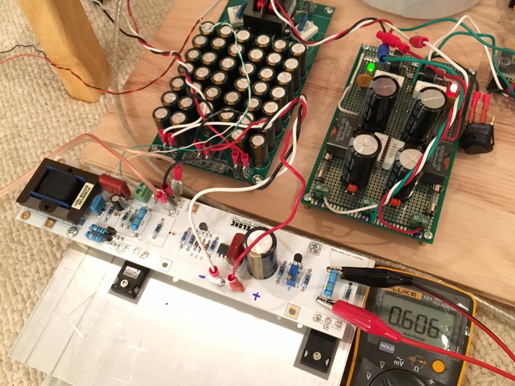
I have qnty 8 x 33mF 25v caps on order. Current class AB PSU is probably not cutting it with about 30mF total for each rail. With both amps hooked up ripple in PSU at amp input is 90mV (is that bad?) and voltage now sags to 23.5v from nominal 25v no load.
@Mr Pass - I am really impressed by the auto-bias circuit here on this amp. Could it be used for lower bias class AB amps where we typically use a temperature compensating BJT thermally mounted to the heatsink to prevent thermal runaway? Is calculation of resistors to set bias current done the same way and even a pot could be used for variable bias adjustment. What keeps the system from thermal runaway as there is no temperature sensor?
I have qnty 8 x 33mF 25v caps on order. Current class AB PSU is probably not cutting it with about 30mF total for each rail. With both amps hooked up ripple in PSU at amp input is 90mV (is that bad?) and voltage now sags to 23.5v from nominal 25v no load.
Last edited:
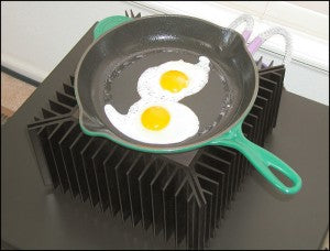
Funny you mention word "Furnace" because I was quite unprepared for how much heat a pair of little IRFP's can put out when running pure class A.
Hi xrk. I don't suppose you could detail the heatsink size you have there? I just chopped a large heatsink from a solar inverter in half, and I'm trying to get a feel for if it's enough for a pass amp.
Thanks!
This amp was a joy to build. Simple simple simple compared to many of the class AB amps I have worked on.
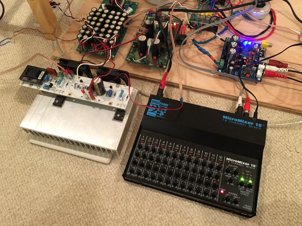
Completed pair of Teabag M2's:
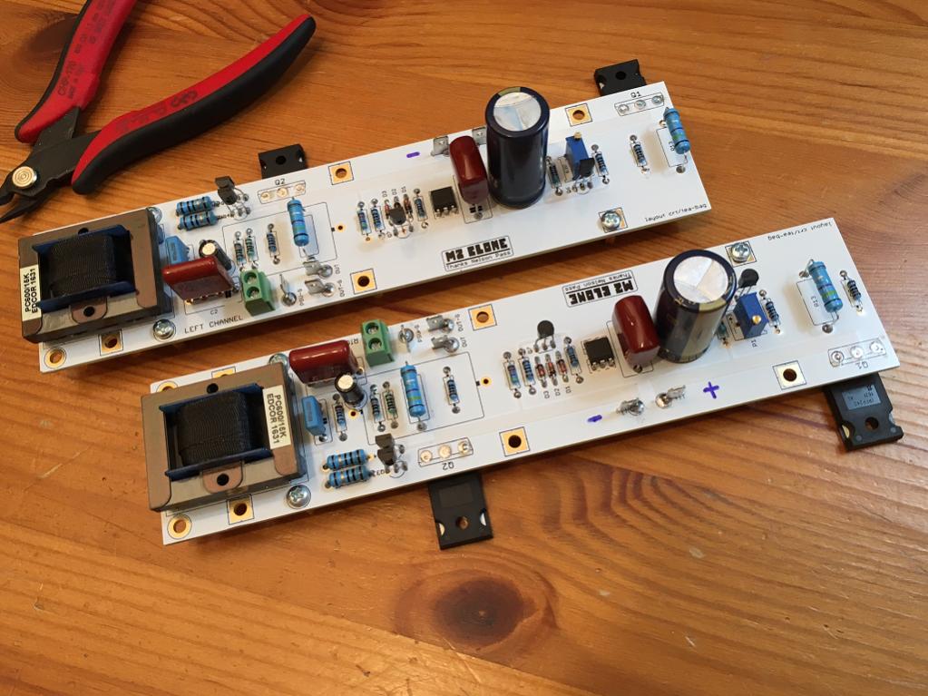
It seems to be running at 1.3A bias current, and the neat thing was to see it start low, and rise fairly quickly once warmed up. I guess had I been listening I would have heard it go through class B, then class AB, then class A
Even with the 52.3k resistor on R7, I could not get the DC offset to zero out. It's bottoming out at -95mV. However, that's not going to stop me from listening.
I am using my existing PSU but with a new 400VA 18vac trafo which makes exactly 25.0vdc rails. Ripple is 56mV with CRCLC filter ending with 20mF of small 1k cap bank and about 29mF total per rail.
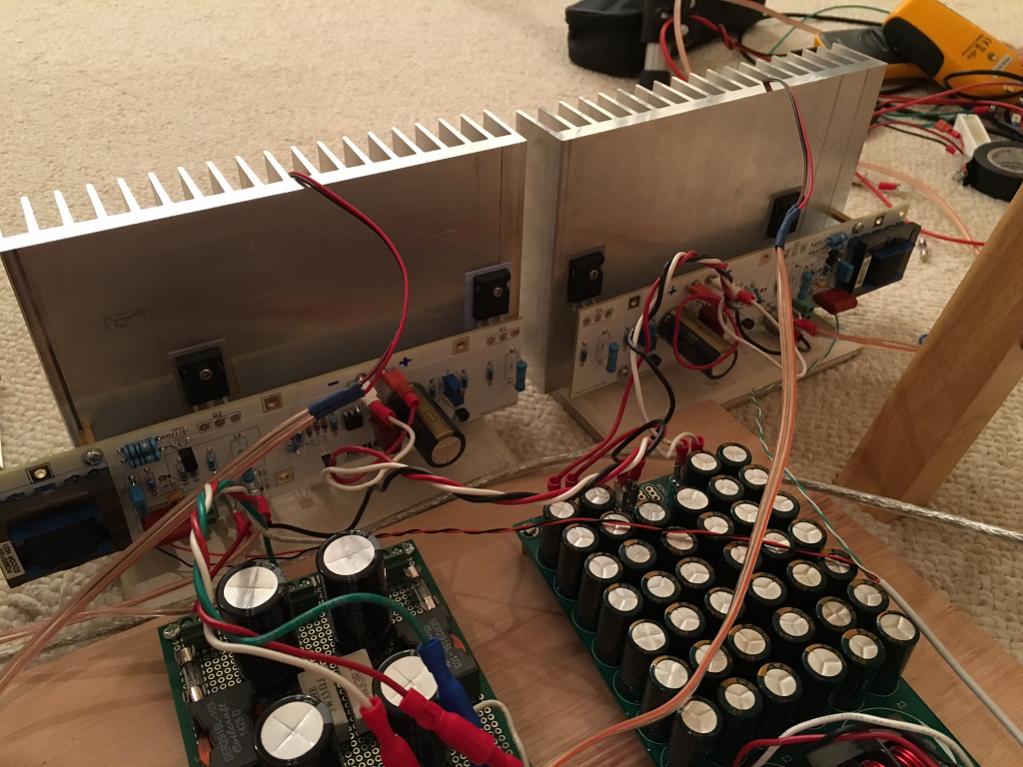
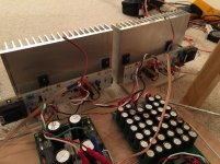
This amp puts out some heat on these slightly undersized heatsinks.
Still listening to it but sounds very good so far. Wish it had more gain
Add BA3 preamp, you gain wishes will be granted...
Russellc
Hi xrk. I don't suppose you could detail the heatsink size you have there? I just chopped a large heatsink from a solar inverter in half, and I'm trying to get a feel for if it's enough for a pass amp.
Thanks!
This is 7.28in wide x 5in tall extrusion, fins are 1in long and base plate is 0.375in thick. It's undersized so I augment with a small 60mm fan at half speed and it's fine. If heatsink was double this size, fully passive would be OK.
Here is the heatsink I used (cut to 5.0in long):
7.280" - HeatsinkUSA
@Mr Pass - I am really impressed by the auto-bias circuit here on this amp. Could it be used for lower bias class AB amps where we typically use a temperature compensating BJT thermally mounted to the heatsink to prevent thermal runaway? Is calculation of resistors to set bias current done the same way and even a pot could be used for variable bias adjustment. What keeps the system from thermal runaway as there is no temperature sensor?
It's a cute little circuit which locks the bias current of the output stage based
on the voltage drop of the opto-isolator LED. It's a more sophisticated
version of my 1987 patent.
Attachments
impedance ratio is going by square of voltage ratio
that means that , in best case - with original 5 V/V autoformer gain , output impedance of buffer+ autoformer combo is 25x output impedance of buffer itself
if you insist on greater voltage ratio (say 10 V/V) , be prepared to have output impedance of buffer+autoformer combo in vicinity of 100x of buffer Rout
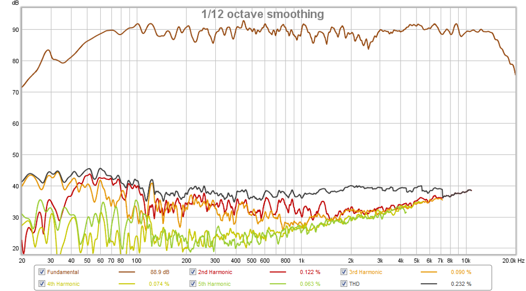
I am getting rather large measurements of H3 distortion at the speaker (normally not present with other amps). M2 seems to have a signature of higher than normal third harmonic from low bass to about 500Hz. Is this normal or is it something off? I am reading that the autoformer may be cause of this signature.
See speaker RTA's here:
http://www.diyaudio.com/forums/soli...audition-very-simple-quasi-mosfet-amp-17.html
Here is Harmonic profile with 200Hz excitation:
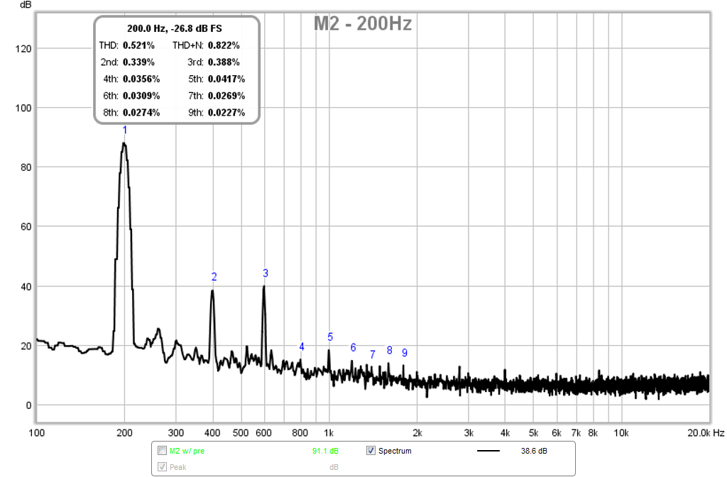
Here is speaker measured harmonic distortion (normally the HD is flat below 500Hz but notice the big bulging rise here).
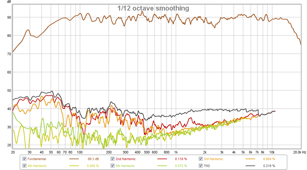
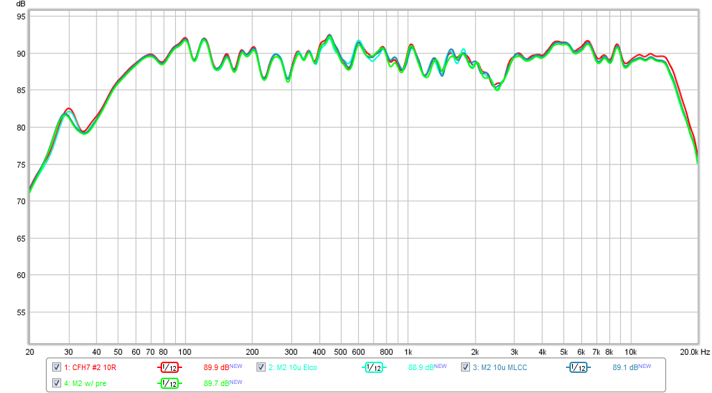
Compared to my CFH7 amp (same IRFP240/9240 outputs but CFA topology) at same condition for speaker and mic and SPL:
The frequency response of the two amps, and M2 with and without preamp are pretty much spot on:
See speaker RTA's here:
http://www.diyaudio.com/forums/soli...audition-very-simple-quasi-mosfet-amp-17.html
Here is Harmonic profile with 200Hz excitation:
Here is speaker measured harmonic distortion (normally the HD is flat below 500Hz but notice the big bulging rise here).
Compared to my CFH7 amp (same IRFP240/9240 outputs but CFA topology) at same condition for speaker and mic and SPL:
The frequency response of the two amps, and M2 with and without preamp are pretty much spot on:
Last edited:
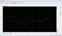
When I measured mine some time ago I got similar results, I think it is the xformer doing this.
My M2 clone is clearly k3 dominant. But this is all written by Nelson in his M2 manual and you can see it in the residual character.
My M2 clone is clearly k3 dominant. But this is all written by Nelson in his M2 manual and you can see it in the residual character.
Attachments
Last edited:
When I measured mine some time ago I got similar results, I think it is the xformer doing this.
My M2 clone is clearly k3 dominant. But this is all written by Nelson in his M2 manual and you can see it in the residual character.
Thanks for the plot - pretty much follows the same trend in the rise of THD and H3 on my speaker data.
I am not so sure I can live with this signature as I am very sensitive to distortion, especially 3rd harmonic.

Thanks for the plot - pretty much follows the same trend in the rise of THD and H3 on my speaker data.
I am not so sure I can live with this signature as I am very sensitive to distortion, especially 3rd harmonic.
Hi,
I've been using a production unit for over four years. For my taste, much like ZM, it's one of the greats. It emulates a valve sound with none of the drawbacks save heat.
and I can add that I measured a real FW M2 too and it has this data too.
I was also a bit concerned when I saw this plots…..
But it does in no way impede my pleasure to hear M2.
This was for me am example how an k3 dominant amp can sound like a k2 amp!
And I do not why…..))
I was also a bit concerned when I saw this plots…..
But it does in no way impede my pleasure to hear M2.
This was for me am example how an k3 dominant amp can sound like a k2 amp!
And I do not why…..
))Hmmm. I'd venture to say that our sensitivity to said distortion below 100 Hz is not the same as it is in the mid band. With few exceptions, it's extremely difficult to find, design or build a transformer without rising distortion in the bottom octaves. I will say the amp deserves the Best preamp that you can afford or build.
- Home
- Amplifiers
- Pass Labs
- Official M2 schematic