Belaji - look (below).
The "price you pay" for full power 5ppm ! (with the caps).
I knew there was no "free lunch" here.
This amp DID have very nice rounded clip.
OS
Add 470n cap make amp oscillated when clip but without cap, it "sticky".
Add 470n cap make amp oscillated when clip but without cap, it "sticky".
Correct solution would be using lower VAS Re, since bypass caps do just that, lower Re - higher OLG, lower distortions.
Add 470n cap make amp oscillated when clip but without cap, it "sticky".
No "sticky" ?? at a slight clip. but at 3V input - yes.
OK , the E staurt. mod did that. Back to the non "folded"
original version (below) .... nice rounded clipping again.
All these mods had a "price" (somewhere ??).
Analog design is all about compromise.
I could actually add these 2 mods to the PCB (2 pads + jumpers) , they don't affect
my main concern of thermal stability.
OS
Attachments
Now mine don't either.
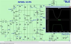
Try this .... with both overload and 4vpp (below).
-original with .22uF Re bypasses.
4ppm thd20 + perfect clip.
OS
Right! Usually I don't have large emitter Rs like you do here. Mine don't stick.
Try this .... with both overload and 4vpp (below).
-original with .22uF Re bypasses.
4ppm thd20 + perfect clip.
OS
Attachments
Do you think a super-pair would be worth trying after all the changes to the front end?
Screw the super pair
.This "rocks" with 4ppm 120V + perfect clip.
I know it has (did have) perfect clip - Thimios abused the hell out of it.
I don't want Thimios/stillforgiven to etch another "dud" , so I go
with what I know works.
OS
Try this .... with both overload and 4vpp (below).
-original with .22uF Re bypasses.
4ppm thd20 + perfect clip.
OS
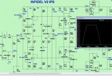
Hmmm , this amp now REALLY performs (it's "sunk" in now).
Are there 2 feedback paths here now ?? , one to the VAS and one to the
input stage. Setting the bias perfect gives VERY low THD !
OS
Hey Pete,
Looking at post 5555, I still don't see how you have adjusted the DC bias current of the TISes. Are you sure it was set (restored) to 5.2mA? If not, your results might not be representative.
Cheers, E.
Hey Pete,
Looking at post 5555, I still don't see how you have adjusted the DC bias current of the TISes. Are you sure it was set (restored) to 5.2mA? If not, your results might not be representative.
Cheers, E.
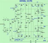
Everything has worked out
.(below) is what I plan to prototype (PCB).
-Your contribution is "OPT1". A builder can set a jumper (note on schema) ,
and have that (folded) configuration. PS - 120R (R22/29) for re-establishing that
5.2ma in the "folded option".
-BV's idea is R4/5 - R17/18 - C5/6.
-Belaji's idea is to bypass the main VAS re's. This is "OPT2" , one could
either add them or omit them.
- Even my idea of mirroring the VAS could be jumpered out on the
Q9/10 pads (omit them / B-E jumpers).
The reason for all of this , even as it will not be too difficult to implement ...
is to "cover thy ar$e" and to allow for the event of "simulator divergence" ..
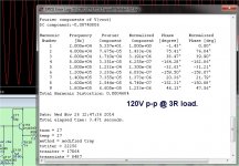
.As far as performance - I can't complain about (below 2) @ 3R on the EF3.
Matches my TMC "wolverine" in this metric.
OS
Attachments
Last edited:
Everything has worked out
(below) is what I plan to prototype (PCB).
-Your contribution is "OPT1". A builder can set a jumper (note on schema) ,
and have that (folded) configuration. PS - 120R (R22/29) for re-establishing that
5.2ma in the "folded option".
[snip]
OS
Hi Pete,
That's one way to reestablish Iq, though it will increase the gain. Maybe some people don't like this (for whatever reason) and prefer to do it with an additional R between the base of Q12 and Q14. This way one can tailor the gain and Iq independently.
Cheers, E.

Hi Pete,
That's one way to reestablish Iq, though it will increase the gain. Maybe some people don't like this (for whatever reason) and prefer to do it with an additional R between the base of Q12 and Q14. This way one can tailor the gain and Iq independently.
Cheers, E.
If they do increase the gain , my margin is WAY past the point where it would do
any harm. With this simple comp. - thimios tried 12p and STILL no overshoot.
What would be your opinion on thermally coupling the Tis's ?
(Q)1/2/5/7 together + (Q)3/4/6/8 ..... all in mutual bondage
?OS
Last edited:
Regarding schematic post 5575 "v2" A. have you tried with a serie regulator to raise PSRR inputstage q1 and q2?
B. What is slewrate for this amplifier?
A. The output stage already has a cap multiplier per rail.
B. This one is not like a typical VFA. In a previous post - I got 1KV/uS
slew in simulation.
OS
- Home
- Amplifiers
- Solid State
- Slewmaster - CFA vs. VFA "Rumble"