1381e/3503d "mismatch" .
Theoretically, with random sampling, 1381e (PNP) should match with 3503d (NPN). Because NPN tends to be better than PNP. Too bad this isn't the case with yours.
D: 60 - 120
E: 100 - 200
So you see, there is 100-120 overlap there. We are expecting PNP/1381/E to be on the lower side and NPN/3503/D to be on the higher side.
Consider also that in the amplifying chain, signal usually goes from NPN (better) to PNP (worse) to NPN (better) and so on (while the exact opposite happens on the other rail), so they kind of "compensate" for each other. And nothing you can do with the output transistor. The NPN is always superior.
Last edited:

SMD VAS ....
Here's the perfect low Cob 400V 1amp SMD VAS pair.
http://www.nxp.com/documents/data_sheet/PBHV8140Z.pdf
.54 cents apiece.
-nearly a perfect match PNP/NPN , only 10%.
Then , for say ... the CFA-X , http://www.centralsemi.com/pdfs/products/pa_dual_sot228.pdf
There is your input matched pair ... in one package. Some are 1% P/N Hfe - but
cost more.
OS
For the first....i can't see the complementary pnpHere's the perfect low Cob 400V 1amp SMD VAS pair.
http://www.nxp.com/documents/data_sheet/PBHV8140Z.pdf
.54 cents apiece.
-nearly a perfect match PNP/NPN , only 10%.
Then , for say ... the CFA-X , http://www.centralsemi.com/pdfs/products/pa_dual_sot228.pdf
There is your input matched pair ... in one package. Some are 1% P/N Hfe - but
cost more.
OS
For the sec. Mouser have not this.

Theoretically, with random sampling, 1381e (PNP) should match with 3503d (NPN). Because NPN tends to be better than PNP. Too bad this isn't the case with yours.
D: 60 - 120
E: 100 - 200
So you see, there is 100-120 overlap there. We are expecting PNP/1381/E to be on the lower side and NPN/3503/D to be on the higher side.
Some do , I have D's over 120 and E's under 140. I could get close with a few.
Also my meter is testing with 9V Vce for beta. At 30-80V , things could be
different. I would not trust the cheap meter ... 100%.
PS - I'm about to go "real" - so I test everything before it is stuffed.
OS
For the first....i can't see the complementary pnp
For the sec. Mouser have not this.
PBHV9540Z,115 NXP Semiconductors | Mouser
OS
Yes.
1 = "sacrificial" amp for testing crazy new ideas out on. Will do the "thimios" thing and
run a single pair of MT200's with a 50-0-50V supply.
2 = Sub amp - 3 pair MT-200 Sanken/12A SOA total @ the 55V rails that EvanC's
trafo will supply. NO cap multiplier with a 100pF compensated wolverine. Have everything for this one.
3/4 = the main amp - 5 pair 0281/0302's ON's with the sanken MT-100's as drivers.
With Valerie's trafo - it really gives 55Vac /almost 80V rails. Only 10 output Re's were in the package.
Hopefully , the returned caps were credited for this amps
power supply.
JW , your metal working capabilities are impressive - such tight perfect bends !!
My case is only a 3U , you and valerie made the protection PCB HUGE !
Now , I could just use it for the sub. .... OR , cut the mains section off and wire
the little trafo /softstart/ac "stuff" externally.
Those (well bent ) big "L" brackets are perfect for adding these extras.
PS - I'm building all 6 amps , I have trafo's/PS's for all of them.
Thank you VERY much , at 95% - I'll go all the way.
OS
Attachments
The protection board was a sample to give you some ideas for yours. It would be good to use on your sacrificial test amp as is. It's fast enough to save some parts when you have a bad idea. If you want to use Valery's design in your amps I have a shrunk down version drawn up with an external transformer I haven't gotten around to having etched yet.
You're going to be short some small caps too. Let us know what you're missing when you get everything assembled and I'll see what I can come up with.
You're going to be short some small caps too. Let us know what you're missing when you get everything assembled and I'll see what I can come up with.
Would it be a good idea to use 10 watt RE resistors with those MT200 devices? They are double the current output of a TO247.
A 5 watter is overkill even for a MT-200. You would have to get up to 350-400mv
(across a .22R) to reach 5W dissipation. By then , even a MT-200 would be "toast".
PS - you can use 3W .22R 's on MT-100's (I've seen this on OEM).
OS
The centralsemi link, does NOT work
For you ...
. No, really - the internet is not perfect.The point is ... that the monolithic P/N packages overcome the gender limitations
of through- hole devices. No need for servo's - postage stamp size VSSA/CFA-X's.
OS
OS,
May I assume that the dimension you listed for the small smd design is only for the input section? Could we make a single all in one board with smd devices and perhaps leave only the output devices as thru hole large devices or are there also smd output devices that can compete with the larger thru hole components? I do have a pair of Lazy Cats VSSA boards and they are just so small, but of course only use a single pair of output devices so not exactly the same as a five pair EF3 design! With a talented layout designer how small could we actually build a completed Krypton C / 0S Slewmaster smd design?
May I assume that the dimension you listed for the small smd design is only for the input section? Could we make a single all in one board with smd devices and perhaps leave only the output devices as thru hole large devices or are there also smd output devices that can compete with the larger thru hole components? I do have a pair of Lazy Cats VSSA boards and they are just so small, but of course only use a single pair of output devices so not exactly the same as a five pair EF3 design! With a talented layout designer how small could we actually build a completed Krypton C / 0S Slewmaster smd design?
OS,
May I assume that the dimension you listed for the small smd design is only for the input section? Could we make a single all in one board with smd devices and perhaps leave only the output devices as thru hole large devices or are there also smd output devices that can compete with the larger thru hole components? I do have a pair of Lazy Cats VSSA boards and they are just so small, but of course only use a single pair of output devices so not exactly the same as a five pair EF3 design! With a talented layout designer how small could we actually build a completed Krypton C / 0S Slewmaster smd design?
Consider that most of the output stage is high voltage/high current.
Most resistors can see over 150V. Most smd resistors are <200V - less
choice for values (looked at the mouser SMD 1/4w EIC tables).
The cap multiplier/predriver area of the OPS could save 20-30mm with SMD ,
but the power section is all cap and output. (NO SMD MT-200's
).IPS's are different story.. LED's , zeners, resistors,semi's ... ALL SMD and cheap !
Just outputs , trimmer , euro's would have to be through hole.
Kypton C would be a good candidate , as would the "eyesee" - I forsee 25mm x
25mm for the "core" circuit. (a 76mm X 35mm IPS) !
PS - "a talented designer" Hmmmmm ?? I could do it - it actually seems easier than through hole.
Edit - 1-2 pair OPS with smd cap multiplier/smd IPS = 76mm X 100mm - 125mm total amp size.
OS
Last edited:
I sometimes use the THAT dual NPN-PNP for current source and inputpair those are good for thermals, but suffer in PNP-NPN matching.
I have made a phonostage, where the input-stage was made with biss transistors, they were really good and very very quiet RBB<3ohm, but so tiny that even good SMD machines had a difficult time placing them , so there I would thing that BISS also had a good chance of sounding good in a poweramp, especially if NPN-PNP matching is really good.
I have made a phonostage, where the input-stage was made with biss transistors, they were really good and very very quiet RBB<3ohm, but so tiny that even good SMD machines had a difficult time placing them , so there I would thing that BISS also had a good chance of sounding good in a poweramp, especially if NPN-PNP matching is really good.
... how small could we actually build a completed Krypton C / 0S Slewmaster smd design?
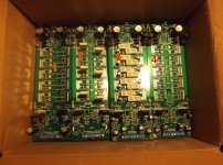
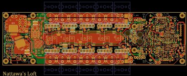
I have a 5-pair layout using SMD front end on a 230x67 mm^2 outline for one of my own VFA project. I think it can easily accommodate any of OS's designs. It includes an on-board solid state speaker protection relay. A DC detector and over-current sensing circuit to trigger that relay are also on board. If the protection part of the circuit is not wanted, about 20 mm can be taken off the size of the PCB.
Attachments
- Home
- Amplifiers
- Solid State
- Slewmaster - CFA vs. VFA "Rumble"