This schematic worked but clipped funny. OS suggested adding anti-facing diodes to curb the weird clipping. I wish I had tried that before I pulled the super pair. If I get feeling spunky, I may put everything back and try the clamp just for fun.
Here is the one thimios said was so good "singing".
I think it performs much worse with the super-pair.
OS
Attachments
Yes this is the working schematic (Kypton-v) and i want to have other opinions about the produced soundHere is the one thimios said was so good "singing".
I think it performs much worse with the super-pair.
OS
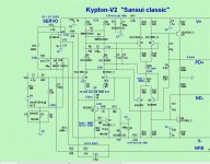
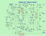
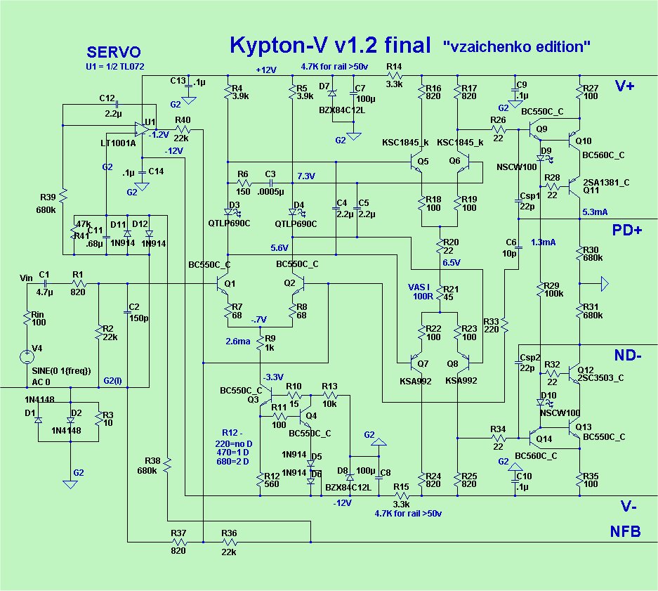
i will soon test kypton V and post my impressions. Are the values in red circles optimal for good phase and gain margins? is there any better combination for better gain and phase margins ?With current values ltspice shows a phase margin of 81.4° and a gain margin of about 16dB. a gain margin of about 20dB would be better..
Attachments
Last edited:
Here is the one thimios said was so good "singing".
I think it performs much worse with the super-pair.
OS
This topology give best PSRR of all audio frequency. It should work with Hawksford cascode VAS. I will try it. My heat sink have arrived few days ago. Now I start make layout.....
Ostripper,
I apologize if this has already been pointed out and I missed it but ...
On the above schematic for Kypton-V2 "Sansui Classic" (Post #5664) Q1 is shown as a KSC1845 device. That's a 'E C B' lead pinout but your PCB drawing is 'C B E' suggesting a BC550C device. What was your intention??
I apologize if this has already been pointed out and I missed it but ...
On the above schematic for Kypton-V2 "Sansui Classic" (Post #5664) Q1 is shown as a KSC1845 device. That's a 'E C B' lead pinout but your PCB drawing is 'C B E' suggesting a BC550C device. What was your intention??
Ostripper,
I apologize if this has already been pointed out and I missed it but ...
On the above schematic for Kypton-V2 "Sansui Classic" (Post #5664) Q1 is shown as a KSC1845 device. That's a 'E C B' lead pinout but your PCB drawing is 'C B E' suggesting a BC550C device. What was your intention??
Functionally , any BJT (or FET) will work with the "V". BCxxx fits the pads , but
ksa/c could be used in a bind(swap leads).
I might of just swapped models for simulation - the "V" first stage is +/- 12V and
can run ANY device.
Sorry I have not been following the thread
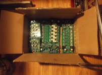
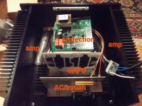
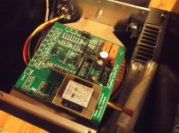
. Been busy with the "superamp". NOT a DIY amp .... it must be like factory !
(below 1-3). Got the arduino protection to fit over the main trafo
.Real happy - 0 screw-ups with this layout. ..... no second chances for this amp.
OS
Attachments
i will soon test kypton V and post my impressions. Are the values in red circles optimal for good phase and gain margins? is there any better combination for better gain and phase margins ?With current values ltspice shows a phase margin of 81.4° and a gain margin of about 16dB. a gain margin of about 20dB would be better..
OK , to the details ....
Your circled R6/C3 set the gain margin , C6/R26 set the bandwidth , C13 will increase margin at unity gain.
All this was simulated for minimal ringing on the square-wave tests. The beta of
the input pair will also be a factor. You might get your 4db margin increase by either
lowering the value of R7/R8 (IP Re) or with a different input pair grade/choice.
Edit - Maouna !!! NO yellow led's - these set the bias for the second stage. Amp is set for
1.6-1.8 V led Vf - yellows are 2.5V+ vf (check this - new ones might not be ??)!!
OS
Last edited:
The amp's looking good so far. I'm in the process of redesigning the protection board on a lot smaller scale. I can send you a couple boards when it's done if you like.
You see the cap/AC/ trafo division for this (smaller chassis)
.I looked at member ASTX's big amp and a few others on the "solid state pix" thread
for ideas.
Forum is FULL of excellent members and advanced techniques !!!!
The Arduino will fit perfect over the toriod. Don't need a small one(PCB).
The cardboard plate you see it on is the key - bolts between the cap plate and the front
panel (over the toriod). PS - need a aluminum one ....
I have many questions on this board after almost completely stuffing it. Will go to
Valerie's thread for it.
Edit - your offer is most gracious , the SUB needs a protect, too . Testing it in that sub box will "shake" any bugs
out !!
OS
Last edited:
This topology give best PSRR of all audio frequency. It should work with Hawksford cascode VAS. I will try it. My heat sink have arrived few days ago. Now I start make layout.....
I tried this amp with the Hawksford , too.
I oscillated even worse than with the Baxandall.
OS
You see the cap/AC/ trafo division for this (smaller chassis)
I looked at member ASTX's big amp and a few others on the "solid state pix" thread
for ideas.
Forum is FULL of excellent members and advanced techniques !!!!
The Arduino will fit perfect over the toriod. Don't need a small one(PCB). The cardboard plate you see it on is the key - bolts between the cap plate and the front
panel (over the toriod). PS - need a aluminum one ....
I have many questions on this board after almost completely stuffing it. Will go to
Valerie's thread for it.
OS
Give me some sort of drawing and I can make the plate up. I can drill it for the board mount standoffs too. I have those dimensions.
Give me some sort of drawing and I can make the plate up. I can drill it for the board mount standoffs too. I have those dimensions.
I can do that ... thanks again .
A question - all my board standoff's are PC 6-32 thread 1/4" ones.
Could I just buy a 6/32 tap and use this thread/tap for both
the output devices and the standoff's ??
Or , is 6-32 too "whimpy" to mount the output devices ?
OS
Did your transformer come with a decent mount for the bottom? I made up a little hub for mine that mounts on the bottom plate of the amp so there's no big ugly nut under it.
The big toriod bolt is not too disturbing , the bottom plate of the chassis is 1/8" plate.
I might get a 2" pcv pipe - fill it with epoxy (with the bolt in it)to put in the middle of the toriod.
ha ha
I not going to run this amp "upside down" !OS
I tried this amp with the Hawksford , too.
I oscillated even worse than with the Baxandall.
OS
OS, you try on real amplifier or simulation?
I found compensation is tricky, must find best value to get good square wave response and no oscillation (in simulation).
OS, you try on real amplifier or simulation?
I found compensation is tricky, must find best value to get good square wave response and no oscillation (in simulation).
If you make it , just make for the ability to jumper out the hawksford.
To your question , yes in simulation it acted strange. This topology seems to "like"
the early effect and lots of Ccb.
OS
OK , to the details ....
Your circled R6/C3 set the gain margin , C6/R26 set the bandwidth , C13 will increase margin at unity gain.
All this was simulated for minimal ringing on the square-wave tests. The beta of
the input pair will also be a factor. You might get your 4db margin increase by either
lowering the value of R7/R8 (IP Re) or with a different input pair grade/choice.
Edit - Maouna !!! NO yellow led's - these set the bias for the second stage. Amp is set for
1.6-1.8 V led Vf - yellows are 2.5V+ vf (check this - new ones might not be ??)!!
OS
Τhanks for replying. I am using BC550C for input pair matched with a beta of around 531. The rest of small signall transistors are TSC2240 GR, TSA970 GR
with a beta of around 320 for the npns and 340 for the pnps.
These yellow leds have a voltage drop of 1.84V each so i guess its fine....For R7/R8 i m using 100ohm resistors. Offset is about 20mV (i dont remember whether positive or negative) even even after 15minutes..
Can anyone who has built kypton v check output offset and post?
About sound impressions.. it has very clear highs...like giving more emphasis in frequencies above 3khz but it lacks a bit at low frequencies.i think kypton C is better there...maybe i have made a mistake somewhere...But these are very personal tastes,depending on equipment used,componnents used so they cannot be taken for granded.
- Home
- Amplifiers
- Solid State
- Slewmaster - CFA vs. VFA "Rumble"