For younger people, the scale of the stroke problem is still quite small - there were a couple of dozen total stroke victims across New York and Philly, and 40% of them were under 50. Compared to the 17,000+ people who have currently died in NYC, its theoretically interesting, but not a huge risk for younger people.
Agreed. The statistics are small for now, but nonetheless important to those studying the affects of Covid-19 on the body, and more importantly why.
Frequency sweep is no problem. No need for stepped sine function. Just plain old sweep like measuring a speaker. What’s hard is stepping the power.
Yes, you're right, the sweep function won't vary the power continuously (or at all). On the other hand, discrete samples at 1w, 10w, 50w will give a good idea of whether it looks more like this:

Or like this:

EDIT:
I did what I should have done originally, and went to look at the TI TPA3255 datasheet. It looks like it may be inherent to the TPA3255.

Last edited:
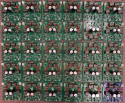
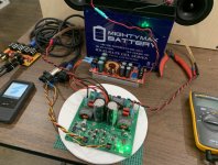
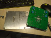
The amps are in! They look great - they all have a "tested" stamp on them, but I will have to check each one for myself to make sure they all work. The one blue one is leftover from the pre-production check build. I am still waiting for the mating PSU and audio input connectors to come in from Mouser. I will include those with the amps so you can start using it right away. Thank you for all your patience on this GB.
Cheers,
X
It looks like a drone shot of a city of amps:


Cheers,
X
It looks like a drone shot of a city of amps:
Attachments
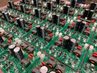
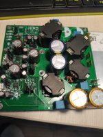
All amps tested and only 1 did not work. I believe it has a damaged 4.7uF cap on the DC-DC buck circuit as no 12v or 3.3v stays lit. No big deal - looks repairable. The order of the connectors for the power, audio in and audio out Molex Minifit also arrived. So I will start shipping out tomorrow!
You all need to order a temporary heatsink and drill and tap two M3 holes on it spaced xxmm apart. You cannot run this amp without a heatsink for more than a minute and only at low power circa 1W. To run at full power of 125w per channel or 250w total, the heatsink needs to remove 10% or 25W. Not a trivial heatsink but a fan cooled GPU cooler works. Or a heat spreader to a large aluminum base.
This heatsink is good for about 10w dissipation or 50w per channel out of the amp.
OdiySurveil(TM) 100 x 40 x 20MM Aluminium Heatsink Radiator Diffusion Cooling Fin Comb Heat Sink Cooler Amazon.com: OdiySurveil(TM) 100 x 40 x 20MM Aluminium Heatsink Radiator Diffusion Cooling Fin Comb Heat Sink Cooler: Computers & Accessories
Or this:
US $2.19 | Free shipping ! Aluminum Heatsink with fan for 5W/10W LED light Cooling Cooler DC12V
Free shipping ! Aluminum Heatsink with fan for 5W/10W LED light Cooling Cooler DC12V|fan regulator|heatsink for led lightfan model - AliExpress
You need to use a 2mm thick copper spacer between the TPA chip and the heatsink to clear the height of the nearby components. Use thermal paste. Tighten the screws gently and don’t overdo it or you will break the TPA chip. I found a genuine AMP Faston 0.25in spade terminal tab x 2 is perfect thermal conductor to lift the heatsink up 2mm above the TPA chip.
Last edited:
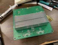
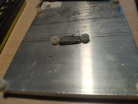
Some detailed photos on how to install a heatsink if you are not going to thermally bond to the chassis floor.
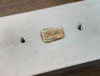
Two M3 holes drilled and tapped 36mm apart, two AMP brand solid copper Faston tabs with thermal paste make a nice 2mm thick thermal spacer to keep the heatsink away from the mounted SMT components. Drill and tap the holes in between the fins for ease of tapping. Be sure not to over tighten mounting M3 bolts and screw them in gently to make sure heatsink is perfectly flat with balanced pressure on each screw. Uneven pressure will not have good heat transfer and may damage the TPA chip with mechanical stress. Also, use preacautions for ESD, like wrist strap.


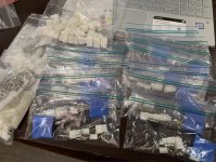
Packaging bags with two 6pin Wurth/Molex quick connects for the speaker outs, Molex 4pin quick connects for PSU in, and two Molex KK 3pins for audio input. Plus all crimp connectors. You would be surprised how long it takes to count all of this out and package it. The cost of the connectors was also surprising - about $3 for some shells and pins. It will save users from having to wait for the connectors to come in from Mouser/Digikey etc before they can use their amp. You do need to get some sort of heatsink though if you want to play it louder than 1W.

Two M3 holes drilled and tapped 36mm apart, two AMP brand solid copper Faston tabs with thermal paste make a nice 2mm thick thermal spacer to keep the heatsink away from the mounted SMT components. Drill and tap the holes in between the fins for ease of tapping. Be sure not to over tighten mounting M3 bolts and screw them in gently to make sure heatsink is perfectly flat with balanced pressure on each screw. Uneven pressure will not have good heat transfer and may damage the TPA chip with mechanical stress. Also, use preacautions for ESD, like wrist strap.
Packaging bags with two 6pin Wurth/Molex quick connects for the speaker outs, Molex 4pin quick connects for PSU in, and two Molex KK 3pins for audio input. Plus all crimp connectors. You would be surprised how long it takes to count all of this out and package it. The cost of the connectors was also surprising - about $3 for some shells and pins. It will save users from having to wait for the connectors to come in from Mouser/Digikey etc before they can use their amp. You do need to get some sort of heatsink though if you want to play it louder than 1W.
Attachments
Last edited:
Hi X,
So, if we elect to go the heatsink route as illustrated... should we mount the PCB upside down to aid in the effectiveness of the HS - letting the heat rise without cooking the PCB over time? I most likely will go with bonding the chip to the amp chassis to distribute the heat.
So, if we elect to go the heatsink route as illustrated... should we mount the PCB upside down to aid in the effectiveness of the HS - letting the heat rise without cooking the PCB over time?
I most likely will go with bonding the chip to the amp chassis to distribute the heat.At normal listening levels like sub 25W, that is 5W dissipation output from heatsink and it doesn't reaally cook the board. If you want to run 100w, definitely use a fan, mount to chassis, or even a bigger heatsink and flip up to allow free air flow to cool, as the one shown is good for maybe 7W dissipation.
Note that if thermally bonding the TPA to a chassis, use an insulator like silicone or ceramic thermal pad to prevent chassis ground from touching amp 0v clean ground.
Note that if thermally bonding the TPA to a chassis, use an insulator like silicone or ceramic thermal pad to prevent chassis ground from touching amp 0v clean ground.
Some detailed photos on how to install a heatsink if you are not going to thermally bond to the chassis floor.
Two M3 holes drilled and tapped 36mm apart, two AMP brand solid copper Faston tabs with thermal paste make a nice 2mm thick thermal spacer to keep the heatsink away from the mounted SMT components. Drill and tap the holes in between the fins for ease of tapping. Be sure not to over tighten mounting M3 bolts and screw them in gently to make sure heatsink is perfectly flat with balanced pressure on each screw. Uneven pressure will not have good heat transfer and may damage the TPA chip with mechanical stress. Also, use preacautions for ESD, like wrist strap.
Hint)))
Attachments
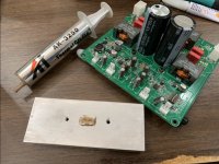
Nylon standoffs or bushings of known thickness can work to keep a constant distance, but you will then need some sort of compressible thermal spacer between the TPA and heatsink to allow the best thermal contact. The compliant spacer is then a bottleneck for heat transfer. I find direct mounting of the heat sink without a bushing a simple way to ensure the best and sure thermal contact.
Very much so, "goop" has horrible thermal transfer characteristics, and it's only intended purpose is to fill microscopic gaps to make better use of contact for thermal transfer. The optimal way to use it is by using just the perfect amount to barely but completely cover the contact between chip/transistor/cpu/whatever and heatsink. The ideal goal is to have as fine a surface as possible so there's hardly any cracks to fill, and to use just enough goop but no more than that. If used excessively it is a perfect insulator, so in the extreme you might end up hindering thermal transfer more than perhaps even convection/air cooling with no heatsink at all.
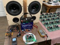
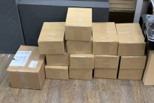
The amps are finally packed. ESD bags, bubble wrap, bag of connectors, box and tape. It’s amazing how much time this always takes. Amps have actually been triple checked - this time on my TL speakers. I want to be absolutely certain that when they are packed, they were working and sounding great. Now, onto making labels. Shipments should go out tomorrow.

Attachments
Last edited:
- Home
- Group Buys
- TPA3255 Reference Design Class D Amp GB