OK i will note this.
thanks for giving the chance to learn something new and usefull.
btw i am not all out from programming but say i am the old school from 85 learning fortran, cobol, etc.
theese days i am almost using matlab and matcad...
.
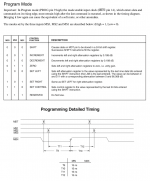
Say why do You used this complicated method for putting together 24 bit MDT word?
first you take decimal number to 8bit binarry value, and latter you cutting out unwanted bits and merging the whole word?
.
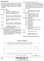
This first method of defining in one line MDT word is OK too and have clear refference to the datasheet?
I am not criticizing just think loud...
// change these settings to configure the PMD100:
byte oversampling_rate = 3; // 1 = 2x oversampling, 2 = 4x oversampling, 3 = 8x oversampling
byte dither_mode = 2; // 0~7 = dither mode 0 to 7
byte input_data_justification = 0; // 0 = left justified, 1 = right justified (16bit)
byte input_bit_clock_polarity = 0; // 0 = rising edge, 1 = falling edge
byte input_frame_sync_polarity = 0; // 0 = LRCI high means left channel, 1 = LRCI low means left channel
byte output_word_length = 0; // 0 = 16bit, 1 = 18bit, 2 = 20bit, 3 = 24bit
byte output_format = 1; // 0 = 2s compliment, 1 = COB
byte output_word_clock_polarity = 0; // 0 = high to low at the end of the output word, 1 = low to high at the end of the output word
byte deglitch_low = 15; // set falling edge of DG to 0~31st interval
byte deglitch_high = 31; // set rising edge of DG to 0~31st interval
// end of settings
uint32_t value = 0;
void configurePMD100() {
value = 0;
value |= uint32_t(dither_mode) << 19;
value |= uint32_t(output_word_length) << 17;
value |= uint32_t(input_frame_sync_polarity) << 16;
value |= uint32_t(deglitch_high) << 11;
value |= uint32_t(deglitch_low) << 6;
value |= uint32_t(output_format) << 5;
value |= uint32_t(output_word_clock_polarity) << 4;
value |= uint32_t(input_data_justification) << 3;
value |= uint32_t(input_bit_clock_polarity) << 2;
value |= uint32_t(oversampling_rate);
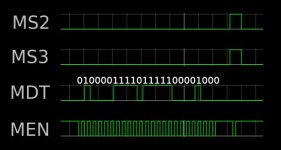
for (int i = 0; i < 24; i++) {
digitalWrite(MEN, LOW);
digitalWrite(MDT, bitRead(value, i));
delayMicroseconds(1);
digitalWrite(MEN, HIGH);
delayMicroseconds(1);
}
")