Go Back   Home > Forums > Blogs

Old

Richard Allan 3 Way Rebuild - So What Do They Look Like?

Posted 26th January 2015 at 09:39 AM by googlyone

The Engineer in me led to plots and graphs, but no pics of the speakers!!!

Click image for larger version

Name:	IMG_2237.JPG
Views:	1683
Size:	965.7 KB
ID:	1540

With a neat old badge...

Click image for larger version

Name:	Richard_Allan_Badge.jpg
Views:	1124
Size:	250.0 KB
ID:	1545

The bass driver is a classic Richard Allan unit, you can tell them a mile away by the red (sometimes blue and black) felt:

Click image for larger version

Name:	IMG_2232.jpg
Views:	1371
Size:	489.2 KB
ID:	1541

The midrange has a fair bit of the B110 about it's looks, though it is smaller and behaves quite differently. This thing is very much a product of it's era (1970's):

Click image for larger version

Name:	IMG_2230.jpg
Views:	996
Size:	580.2 KB
ID:	1542

The surround on the midrange is stated as PVC in some literature I found. I kind of believe this, though it has been coated with something sticky. It is not sticky on the back.

The cabinets were in moderately good condition. There were some coffee stains on the top of one, and water stains on the side of the other. In the end I sanded and revarnished them.

The timber...
Attached Thumbnails
Click image for larger version

Name:	IMG_2225.jpg
Views:	904
Size:	532.2 KB
ID:	1543   Click image for larger version

Name:	IMG_2227.jpg
Views:	882
Size:	401.2 KB
ID:	1544  
diyAudio Member
Posted in Uncategorized
Views 1433 Comments 2 googlyone is offline
Old

MJL21194 Transisors: Real, Second Source and Fake

Posted 6th December 2014 at 05:10 AM by googlyone

Over the last couple of decades I have built an awful lot of power electronics stuff, especially power amplifiers.

So I have bought and used a commensurately large number of power electronic devices.

As a young hobbyist this started with salvaging bits from refuse - especially in the late 70's and early 80's larger power devices were far from cheap. This generally worked really well, as I never did really trust what I pulled out of refuse gear, and I tested stuff that I used. (also not the least as data on power devices came from "equivelant devices" books such as the "Towers guide" and if you were really lucky you found a datasheet somewhere (on paper!). no intenet....

Why the digression?

Oddly with the advent of the internet and subsequently things like EBAY:
- I could get all sorts of things that you just could not buy locally in small quantities.
- Unscrupulous buggers out there started...
Attached Thumbnails
Click image for larger version

Name:	DSC00990.jpg
Views:	1028
Size:	1,015.1 KB
ID:	1454   Click image for larger version

Name:	DSC00979.jpg
Views:	2219
Size:	992.3 KB
ID:	1455   Click image for larger version

Name:	DSC00988.jpg
Views:	962
Size:	780.7 KB
ID:	1456   Click image for larger version

Name:	DSC00985.jpg
Views:	1054
Size:	510.7 KB
ID:	1457  
diyAudio Member
Posted in Uncategorized
Views 2836 Comments 2 googlyone is offline
Old

Integration and test of CS4398 / PIC based Direct Digital Synthesiser

Posted 2nd November 2014 at 05:03 AM by googlyone
Updated 2nd November 2014 at 10:48 AM by googlyone

About 6 months ago I finished off a CS4398 (DAC) and PIC32MX450 (microcontroller) based direct Digital Synthesiser.

I recently packaged this into an instrument case, and added a power supply cum interface card that allows this to all neatly plug together. As a final chapter to the development of this synth, I have tried to measure the harmonics it generates and to use it to test an example amplifier.

What does it look like? Not super fancy, but neat enough and laid out pretty reasonably I think:

Click image for larger version

Name:	opr3-DDS_Internals.jpg
Views:	531
Size:	202.4 KB
ID:	1437

The larger home made board at the back is a power supply - well five of them in fact - to allow clear isolation between a number of digital and analogue rails.

The square board on the base of the case is the PIC board. This runs the human machine interface and more importantly does all the calculation of the waveforms. You can generate any waveform you want, provided it is repetitive and can be...
Attached Thumbnails
Click image for larger version

Name:	opr1-Tiny_Amp_Spectra567Hz No Load.jpg
Views:	173
Size:	68.7 KB
ID:	1435   Click image for larger version

Name:	opr11-Tiny_Amp_Spectra567Hz No Load - fundamental notched.jpg
Views:	160
Size:	68.4 KB
ID:	1436   Click image for larger version

Name:	opr4-DDS_Spectra567Hz Direct Into Soundcard -31dB.jpg
Views:	211
Size:	136.8 KB
ID:	1438   Click image for larger version

Name:	opr5-DDS_Spectra567Hz Fundamental notched -31dB.jpg
Views:	166
Size:	137.4 KB
ID:	1439   Click image for larger version

Name:	opr6-Measurements.jpg
Views:	242
Size:	203.2 KB
ID:	1440  

Click image for larger version

Name:	opr7-Soundcard Shorted.jpg
Views:	180
Size:	135.6 KB
ID:	1441   Click image for larger version

Name:	opr8-Test Rig.jpg
Views:	239
Size:	193.0 KB
ID:	1442   Click image for larger version

Name:	opr9-Test Setup.jpg
Views:	271
Size:	200.8 KB
ID:	1443   Click image for larger version

Name:	opr10-Tiny_Amp_Spectra567Hz 8R Load, Near Clipping.jpg
Views:	162
Size:	68.4 KB
ID:	1444  
diyAudio Member
Posted in Uncategorized
Views 1066 Comments 0 googlyone is offline
Old

Repair of a vintage driver (Richard Allan)

Posted 6th October 2014 at 10:30 AM by googlyone

Over the last 6 or so months I have built a nice little sub plus satellite system that comprises:
- The "Ikea Salad Bowl Speakers", with some really nice vifa premium line drivers in them, making these 1980's vintage
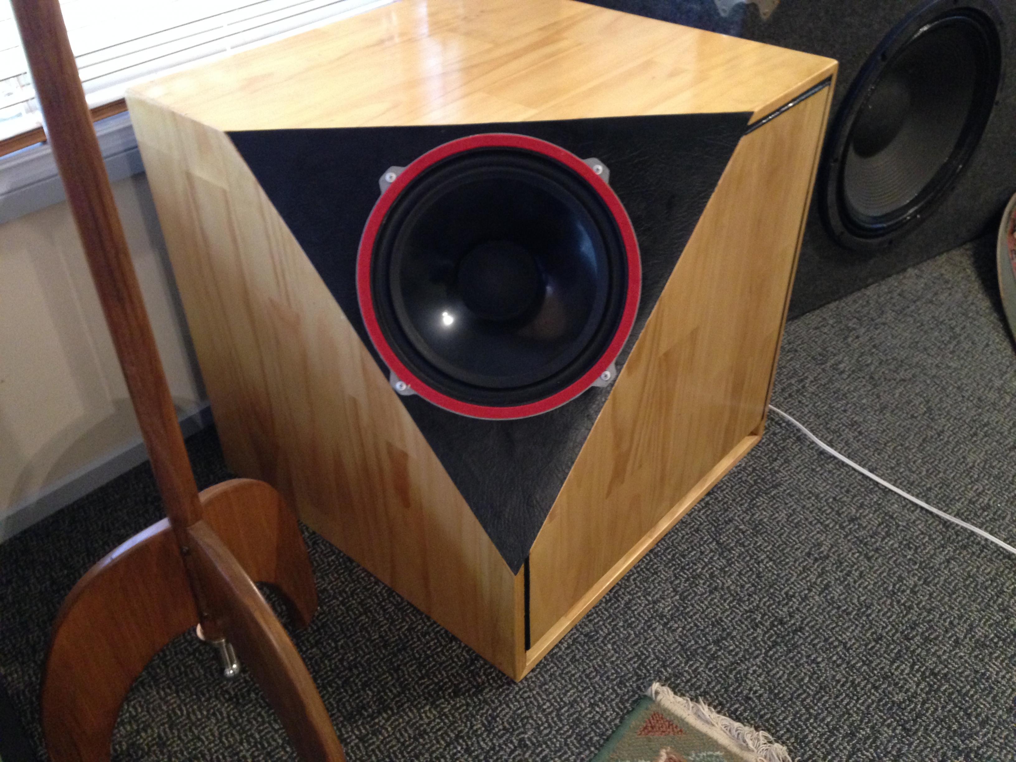
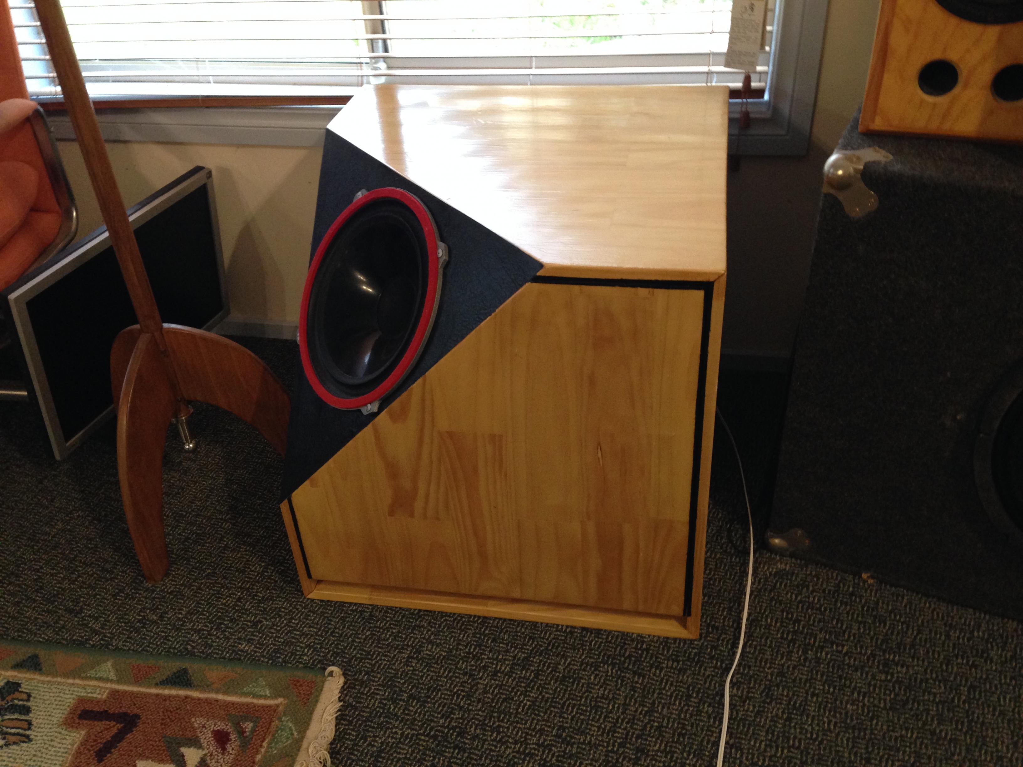
- A Richard Allan subwoofer, in which I used a 1970's (I guess) HP12B driver, in a complex cubical enclosure with a corner cut off for the driver, and
- A ridiculously complex amplifier built to drive this lot, with DSP, multiple channels, optimised even to the point of addressing the fact the HP12B is 16 Ohms, and running bridged for that output.

So imagine my reaction when last night I settled back and ran the system up "properly" for maybe the second or third time, and CRACK!!!

My initial thought was that I had over "excursioned" the sub, and the voice coil was hitting the magnet backplate. I dug into the amplifier and programmed a subsonic filter, as you do, and settled back in again. CRACK!...
Attached Thumbnails
Click image for larger version

Name:	opr2-DSC00582.jpg
Views:	1121
Size:	89.7 KB
ID:	1397   Click image for larger version

Name:	opr3-DSC00583.jpg
Views:	405
Size:	87.8 KB
ID:	1398   Click image for larger version

Name:	opr4-DSC00584.jpg
Views:	996
Size:	77.0 KB
ID:	1399   Click image for larger version

Name:	opr5-DSC00585.jpg
Views:	276
Size:	83.0 KB
ID:	1400   Click image for larger version

Name:	opr6-DSC00589.jpg
Views:	365
Size:	119.3 KB
ID:	1401  

Click image for larger version

Name:	opr8-DSC00593.jpg
Views:	330
Size:	112.8 KB
ID:	1402   Click image for larger version

Name:	opr9-DSC00604.jpg
Views:	218
Size:	98.4 KB
ID:	1403   Click image for larger version

Name:	opr11-DSC00606.jpg
Views:	261
Size:	106.3 KB
ID:	1404  
diyAudio Member
Posted in Uncategorized
Views 1968 Comments 3 googlyone is offline
Old

Retro Amp - final product

Posted 26th August 2014 at 01:18 PM by googlyone

I finally got the retro am finished. At least to the point of all the parts set to work, the case built and assembled and wired up.

The photos really don't show just how orange it is, nor does he slant in the case "pop out" as much as it does in real life.

Click image for larger version

Name:	opr6-IMG_1842.jpg
Views:	302
Size:	126.2 KB
ID:	1376

Yes, I did the "writing" on the front panel by hand with a paintbrush.... I came close to getting the thing CNC milled, but concluded that the hand painted approach would be (a) fun, (b) a new challenge, and (c) more in line with a retro amp

Click image for larger version

Name:	opr3-IMG_1838.jpg
Views:	271
Size:	136.2 KB
ID:	1375

Click image for larger version

Name:	opr7-IMG_1843.jpg
Views:	368
Size:	182.1 KB
ID:	1377

Click image for larger version

Name:	opr8-IMG_1844.jpg
Views:	233
Size:	193.3 KB
ID:	1378

Click image for larger version

Name:	opr10-IMG_1846.jpg
Views:	215
Size:	170.1 KB
ID:	1379

Click image for larger version

Name:	opr11-IMG_1847.jpg
Views:	224
Size:	180.9 KB
ID:	1380

Click image for larger version

Name:	opr15-IMG_1852.jpg
Views:	201
Size:	143.1 KB
ID:	1381

Click image for larger version

Name:	opr16-IMG_1853.jpg
Views:	261
Size:	155.4 KB
ID:	1382

Click image for larger version

Name:	opr18-IMG_1856.jpg
Views:	222
Size:	197.8 KB
ID:	1383

The amplifier has:
- A digitiser on its input.

- DSP implementing crossover and...
diyAudio Member
Posted in Uncategorized
Views 1103 Comments 0 googlyone is offline
Old

DIY Weller WSP80 / WP80 Soldering Station

Posted 24th August 2014 at 08:58 AM by googlyone

I have been using a pretty crappy "Dick Smith" soldering iron for - well too damn long. I have always been meaning to get a decent iron. Given the fact that it worked, and I have been using it for close on 30 years (if not more) resulted in me investing my time and money in other things.

I recently bought two WSP80 Weller soldering irons off ebay at a killer price.

These ate just the "pencil" part of the soldering iron, and need the power supply / controller. Which are not cheap.

Looking on the net there are a number of schematics of various weller power supply / controllers. But various bits and pieces were not quire right for the WPS80 that I had.

As a start I am using this...
Click image for larger version

Name:	Weller_WSP80_PSU.jpg
Views:	10045
Size:	220.9 KB
ID:	1373

This is evidently extremely analogue. Which is quick and easy to design and build, and analogue just warms the cockles of my heart.

The final product is like this......
Attached Thumbnails
Click image for larger version

Name:	opr1-IMG_1831.jpg
Views:	3333
Size:	89.2 KB
ID:	1371   Click image for larger version

Name:	opr2-IMG_1826.jpg
Views:	4241
Size:	110.9 KB
ID:	1372  
diyAudio Member
Posted in Uncategorized
Views 10081 Comments 2 googlyone is offline
Old

Multi Channel Amplifier with DSP Crossover - Retro styling

Posted 13th July 2014 at 02:26 AM by googlyone

What sort of amplifier do you build to go with a funky retro subwoofer and "Ikea Salad Bowl" speakers?

How do you reconcile this with the fact that you have a "metric shitload" of DSP stuff laying around?

I have run into this problem, and concluded that I need to mash these into something that is not new and higher tech than old style.

This has resulted in me trying to train smash "new and old" into what I am hoping will be a retro styled, but thoroughly high tech-on-the-inside amplifier. (Stopping short of going class - D which I hold aesthetic objections against).

So lets get started with the basics. The amplifier will not be square - it will be a parallelogram...

Click image for larger version

Name:	Panel Outline.jpg
Views:	320
Size:	90.8 KB
ID:	1332

And to follow up with my (albeit young) recollections of the 1970's, it CANNOT be black.

This amplifier needs to be the most acid driven shade of orange that I can find....
Attached Thumbnails
Click image for larger version

Name:	Amplifier_Mounting.jpg
Views:	229
Size:	100.2 KB
ID:	1330   Click image for larger version

Name:	DSP_Mounting.jpg
Views:	240
Size:	110.1 KB
ID:	1331   Click image for larger version

Name:	DSP_Image_EndShot.jpg
Views:	735
Size:	184.1 KB
ID:	1333   Click image for larger version

Name:	DSP and Power Supply1.jpg
Views:	630
Size:	182.4 KB
ID:	1334   Click image for larger version

Name:	DSP_Controls.jpg
Views:	397
Size:	124.3 KB
ID:	1335  

Click image for larger version

Name:	Power_Supply and Speaker_Prot.jpg
Views:	601
Size:	144.4 KB
ID:	1336   Click image for larger version

Name:	IMG_1774.jpg
Views:	609
Size:	639.3 KB
ID:	1337   Click image for larger version

Name:	DSP_Regs.jpg
Views:	332
Size:	168.6 KB
ID:	1338  
diyAudio Member
Posted in Uncategorized
Views 1842 Comments 1 googlyone is offline
Old

Cubist Subwoofer to go with Ikea bowl Speakers - just looks wrong!

Posted 1st June 2014 at 12:20 PM by googlyone
Updated 1st June 2014 at 12:24 PM by googlyone

A while back I built some Ikea bowl speakers using Vifa bassmids and tweeters. The performance came out very good indeed, but when you are dealing with a 5 odd inch driver, there will never be masses of bass.

A subwoofer was always on the cards.

Click image for larger version

Name:	IMG_1490_small.jpg
Views:	2651
Size:	661.2 KB
ID:	1298

Given the spherical speakers perched on the retro "rocket like" stands, I initially thought of doing a spherical subwoofer - but in the end concluded that while I could do this, I was looking at using fibreglass on a "fit-ball", placement in the room was looking to be a challenge.

So I chose to do the absolute opposite - and came up with an off the wall approach to a conventional sub.

Click image for larger version

Name:	IMG_1483.jpg
Views:	2194
Size:	739.6 KB
ID:	1296

Click image for larger version

Name:	IMG_1487.jpg
Views:	1299
Size:	631.9 KB
ID:	1297

The idea was to move the implementation of a conventional sub well away from the "box with a driver stuck on the front".

I find it fascinating that...
diyAudio Member
Posted in Uncategorized
Views 1849 Comments 1 googlyone is offline
Old

Simple DSP Crossover implemented using PIC32MX450

Posted 17th March 2014 at 10:49 AM by googlyone
Updated 17th March 2014 at 10:58 AM by googlyone (incomplete)

It must be close to 12 months ago that I saw the PIC32MX450. I was convinced that a chip that included two I2S audio interfaces, and ran at 100MHz implementing 32bit arithmetic in pretty snappy time would surely be able to do some fun audio stuff.

I started with getting a board designed, and porting the code that I use to control my Analog Devices audio DSP. Then I generated the code to implement a direct digital synthesiser. These worked fine.

Over the last couple of weeks I have completed the "core code" for a digital crossover all implemented in the PIC32 itself.

The basic implementation is:
- An analogue to digital converter
- The PIC
- A digital to analogue converter
(Oh and an interface PCB done on veroboard to route the MCLK and power to the A/D and D/As. I am kind of tempted to re-spin the PIC32 board to do this for me...)

The PIC drives the I2S interface as master, generating...
diyAudio Member
Posted in Uncategorized
Views 1791 Comments 4 googlyone is offline
Old

Code for dual channel DDS...

Posted 25th January 2014 at 02:37 PM by googlyone
Updated 26th January 2014 at 06:34 AM by googlyone (Incomplete)

I was asked if I would share the code for the audio DDS I was playing with.

It is here...

Ver0.1.zip

I think this is all the files you need.

To show just how lazy I am, the main function is the file titled "dig_cross.c" - as that was the main function I edited as the base of this code. There is also a file "ad1940.c" which contains a bunch of the SPI stuff. This is yet another illustration of my bone idle-ness - as this module is probably a decade old. It is used, but has nothing to do with an AD1940 IC....

No apologies

There is a bunch of comments in this, but some general overview comments are:
- About 95% of the source code is about:
- Running the user interface
- Generating the display (rather utilitarian implementation)
- Reading from the EEPROM, and doing limit checks on data
- Writing to EEPROM

...
diyAudio Member
Posted in Uncategorized
Views 1021 Comments 0 googlyone is offline

New To Site? Need Help?
Copyright ©1999-2017 diyAudio