@miro1360,
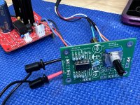
Powered up preamp board, +/-14.4V
Input source connected is an iPhone, but haven’t connected to power amplifier yet. I’m a bit concerned about the output DC offset, a little higher than I’d like to see.
Did you experience the same? Do we need to add an offset trimming circuit?
Powered up preamp board, +/-14.4V
Input source connected is an iPhone, but haven’t connected to power amplifier yet. I’m a bit concerned about the output DC offset, a little higher than I’d like to see.
- HL Output: is 30mV and increases to 40mV as volume pot is increased to 2/3, then drops back to 30mV at max volume.
- HR Output: same behavior but 10mV higher, 40mV to 50mV back to 40mV.
Did you experience the same? Do we need to add an offset trimming circuit?
Attachments
@Vunce Hm, I did not checked it and you are right, we have offset, ****  ... It is caused by that potentiometer, TPA just does not like it (it should be a buffer in the signal path between TPA and potentiometer, or DC servo can solve it) ... I will look for some DC servo solution and will be back ...
... It is caused by that potentiometer, TPA just does not like it (it should be a buffer in the signal path between TPA and potentiometer, or DC servo can solve it) ... I will look for some DC servo solution and will be back ...I had all the parts and a little time. But I'm not going to insert it into the DAC right away, I'm expecting the AD1860 to arrive any day. Since I already have a PCB with AD1856 installed in my DAC, I should try that first.@NIXIE62 That was fast, very nice
Here is my TOP 10 list *(PCM63P)The OPA1641A matched the AD1856 very well. Might be the same with PCM1702 or AD1865, I'll check. It is a cheap OPA with Fet inputs.
1. Muses02
2. Burson V6C
3. New Class D Ultimate edition
4 Sparkos SS3601
5. OPA1641A
6. OPA 1612 / 11
7. OPA 1655
8. OPA 627
9.OPA-2604AP
10 AD797
It remains to hear Muses05 /Muses03.....
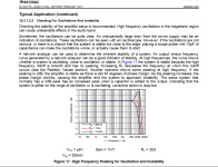
There can be several reasons for such a large offset, the TPA6120 is a CFA amplifier and therefore requires a little more attention regarding the decoupling as well as the PCB itself.@miro1360,
Powered up preamp board, +/-14.4V
Input source connected is an iPhone, but haven’t connected to power amplifier yet. I’m a bit concerned about the output DC offset, a little higher than I’d like to see.
- HL Output: is 30mV and increases to 40mV as volume pot is increased to 2/3, then drops back to 30mV at max volume.
- HR Output: same behavior but 10mV higher, 40mV to 50mV back to 40mV.
Did you experience the same? Do we need to add an offset trimming circuit?
I would first check if the TPA6120 oscillates and then change some components including the red Wima which are not good for CFA, if even after that the offset is large I would insert an op-amp between volume pot and the TPA6120.
Attachments
@grunf The offset is caused by the R2 and R7 value and also the 10k potentiometer. Removing R2 and R7 decrease this offset, but 10k potentiometer will still hold DC offset around 15mV, which is probably too much for a preamp  Adding opamp into the signal way means changing the sound so probably only servo can do the job and hold the offset under 1mV ...
Adding opamp into the signal way means changing the sound so probably only servo can do the job and hold the offset under 1mV ...Need some power supply help here please .
i am building PCM1702 dac with discrete I/V stage .
dac requires +-5v for both digital and analog while I/V stage requires +-15v .
i don't intend to use separate power supplies for 5v as datasheet of PCM1702 states there is no benefit in doing so :
''Both positive supplies should be tied together at a single
point. Similarly, both negative supplies should be connected
together. No real advantage is gained by using separate
analog and digital supplies. It is more important that both
these supplies be as “clean” as possible to reduce coupling
of supply noise to the output.''
i have populated PSU2 for +-5v and +-15v by changing the appropriate resistors .
i have transformer with dual 15v outputs . According to my calculations 15VA is enough .
The hesitation i have is for 15v AC input to 5v DC output . wouldn't it convert to heat for the LDOs such
a big dropout voltage ? or am i just overthinking about it because the current consumption is low ?
DAC chip is where conversion take a place.Need some power supply help here please .
So the power supplies marked as Vdigital and Vanalog are in the same time digital and analog.
BUT onlly if You have digita lisolators before DAC chip. AND if You have analog (transformer galvanic) isolation AFTER the Riv or other circuit after the same signal is pure analog...
.
The diagram is simple, and for true barier between modules in chain it is like this
Digital + iso + DAC + iso + Analog
PS digi........+ .PS d/a......+ PS analog.
.
You can "merge" together all of these different grounds and it will work of course.
this is my concern mostly .. 15v AC after filter would be 19-20v DCThe hesitation i have is for 15v AC input to 5v DC output . wouldn't it convert to heat for the LDOs such
a big dropout voltage ? or am i just overthinking about it because the current consumption is low ?
After rectification diodes, yes. It depends on the diode Vf. For this psu 2 ldo, its enough. For low consuption, it's good to have bit more vin to regulator, it does heat a bit more, but psrr is usually better. If you feed 5V ldo with it, it's also ok as long as you heatsink it properly, but i'd get another transformer.
@floyd89gr, you seem to be concerned if the 5 VDC ldo will heat up too much. and that is a valid concern. As you build your own combinations, you will likely need to know if you are exceeding a power disipation (Pd) limit of a component many times. Since you are not alone with this problem, I will give some general advise to help you and the others. You are not helpless and at the mercy of other people's opinions; you can figure this out. Do a search, like a google search on how to calculate the heat a component will produce. A few tips, start out by looking at the data sheet (DS) of the 1702 and find how much current it draws and add up all the current load on the ldo. Also, check the ldo DS. You know Ohm's law, that P=E x I, so you will multiply the total current load by the voltage drop on the ldo. In this case, miro already specified a good heat sink for the PSU2, which likely is enough for you situation, but you can search for a heat sink with slightly better heat transfer (google how heat sinks are rated) to be safe. After you build it, you can use an inexpensive infrared thermometer to double check the temperature of your ldo to be sure.
In short, if you calculate things yourself, you will tend to enjoy this hobby even more.
In short, if you calculate things yourself, you will tend to enjoy this hobby even more.
I would use a transformer with 7+7 VAC and one PSUD2 with 4 regulators for the DAC chip. It means -+5VDC for the digital part and separately +-5V for the analog part, so that each voltage has its own regulator. Then some other power supply for I/O (but not PSUD2 because it cannot work with a 15+15VAC transformer). Or to use PSUD2 with two regulators and transformer with 12+12VAC. It is LDO so it can provide at least +-14V DC.
- Home
- Source & Line
- Digital Line Level
- DAC AD1862: Almost THT, I2S input, NOS, R-2R