In this case, I think both of you are in agreement, but just different use of terminology.
No thats not actually true.
How would one explain compression drivers not having a dip at the frequency of second peak of higher frequency?
In fact, there is generally a peak in the SPL just above the second impedance peak, not a dip. You really need to look at the topology to understand this. It took me a while to sort it out, and the confusion about it here is very typical.
Think of the diaphragm and horn as being a coupled two mass system with the diapragm mass and the waveguide mass being the two masses. They are coupled together by the compliance of the air between the diaphragm and the phase plug. The two peaks are the two resonances of this two degree of freedom system. The lower one has both masses moving in phase, but the radiation is low since the frequency and efficiency are low. The second resonance occurs when the two masses are moving in opposition. This resonance is quite pronounced and results is a large peak in the SPL at the second resonance.
Well, the referenced paper talks about the volume in front of the diaphram. So how is it different from what you were talking about?No thats not actually true.
In fact, there is generally a peak in the SPL just above the second impedance peak, not a dip. You really need to look at the topology to understand this. It took me a while to sort it out, and the confusion about it here is very typical.
Think of the diaphragm and horn as being a coupled two mass system with the diapragm mass and the waveguide mass being the two masses. They are coupled together by the compliance of the air between the diaphragm and the phase plug. The two peaks are the two resonances of this two degree of freedom system. The lower one has both masses moving in phase, but the radiation is low since the frequency and efficiency are low. The second resonance occurs when the two masses are moving in opposition. This resonance is quite pronounced and results is a large peak in the SPL at the second resonance.
Additionally, the curve posted here http://www.diyaudio.com/forums/multi-way/140190-jean-michel-lecleach-horns-63.html#post2070545 is an efficiency plot. Interestingly, the SPL curve does not show anything significant. I wonder what hole this driver is famous for?🙄
Well, the referenced paper talks about the volume in front of the diaphram. So how is it different from what you were talking about?
An air volume which is in series with the wave propagation - the wave moves through it - is quite different from a volume which is in parallel - the wave does not move through it, but into it. They are completely different things.
hey guys,
can anyone please translate the "Notice" in the horn calculation spreadsheet by Mr. Le Cleac'h? I'm trying to understand the spreadsheet but whenever i modify the values in the colored cells, it seems that no horn profile is being shown in the horn profile sheet.
Notice:
Cette feuille de calculs est destinée aux pavillons dont deux parois sont parallèles, l'expansion se fait donc uniquement dans un plan. (On pourrait aussi appeler ces pavillons: pavillons radiaux). Le pavillon de grave de Monsieur Roggero est un pavillon de ce type. Une option permet d'utiliser un mur de la salle d'écoute comme élément de symétrie, c'est ce qui conduit aux pavillons d'extrème grave les plus courts.
Pour alléger le fichier, la feuille est livrée vide de ces lignes de calcul. Pour permettre le calcul de tous les points, il faut dans la feuille "Horn calculation" recopier la ligne 34 depuis la ligne 35 jusqu'a la ligne 4035.
Utilisation:
Le choix des paramètres s'effectue dans la feuille "Horn calculation".
En case B10, choisir la fréquence de coupure basse acoustique, sachant qu'il est souhaitable de couper électriquement une octave au dessus.
En case B11, indiquer le diamètre de gorge ou sortie moteur, en mm.
En B14, on peut choisir le type d'expansion, 1 dans le cas d'un expo, 0 pour un hyperbolique. La valeur usuelle pour un pavillon de médium sera de 0.707(hypex).
En B19, on choisi un coefficient qui définit le type de pavillon , rond ou carré. 3,14 pour un pavillon rond et 4 pour un carré.
En B37, un coefficient permet si l'on utilise les pavillons en coin de pièce, de tenir compte des murs de cotés qui prolongent le pavillon. 2 par défaut si l'on ne tient pas compte des murs (cas général) et 1 avec les murs.
Choisir les paramètres, laisser Excel calculer (qq secondes) et visionner le résultat sur : la feuille Half horn profile qui dessine le profil.
Is the plateau right side of the resonance peak in your simu due to the horn's performance, or did you enter special motor parameters for that?
Hi Michael,
The Hornresp simulation model takes both the horn and driver characteristics into consideration when calculating the loudspeaker electrical impedance. The input parameters used by the program are as detailed in my previous post. No additional "special motor parameters" are required.
Kind regards,
David
So what driver is structured the way you describe?An air volume which is in series with the wave propagation - the wave moves through it - is quite different from a volume which is in parallel - the wave does not move through it, but into it. They are completely different things.
can anyone please translate the "Notice"
This worksheet is for horns with two walls are parallel, the expansion is therefore only a plan. (One might also call these horn: radial horn). The Mr. Roggero bass horn is an horn of this type. One option permit to use one wall of the listening room as an element of symmetry, it's what leads to short extreme Bass horn.
To enable calculation of all items must be in the worksheet "Horn calculation" copy the line 34 from line 35 to line 4035.
Use:
The choice of parameters is carried out in the paper "Horn calculation".
In cell B10, choose the acoustic bass cutoff frequency, knowing that it is desirable to electrically cut an octave above.
In cell B11, enter the diameter of throat or motor output, in mm.
In B14, we can choose the type of expansion, 1 in the case of an exponential, 0 for a hyperbolic. The usual value for a horn of medium will be 0,707 (Hypex).
Choose the settings, let Excel calculate (few seconds) and see the result of: "Half horn profile" sheet that draws the profile.
Hello,
One of the main origin of the multiple peaks on the impedance curve of a compression driver is the horn itself.
Horns producing reflections from mouth (or whatever rapid flare change) to diaphragm show impedance curves with such multiple peaks.
As an example let' see the attached file. This is a graph showing 2 simulated impedance curves obtained using Hornresp. Both simulations use my equivalent model for the TD2001 driver: the first curve is for a Le Cléac'h horn (Fc = 320Hz, T = 0.8) the second is for an exponential horn of the same cut off frequency and the same length.
While there is no mutiple peaks on the impedance curve of the TD2001 on the Le Cleac'h horn we can see several ones on the impedance peaks of the exponential horn.
If reflected waves can have such effect on the diaphragm mobility and therefore on the impedance curves why a resonating cavity as the one at the rear of the coil should not have its effect on the impedance curve?
Best regards from Paris, France
Jean-Michel Le Cléac'h
I never said that the cavity resonance does not exist in that driver, it does, and in many others as well. I said that it was NOT the reason for the second peak, which is what you stated and was incorrect. The cavity resonance will only be a very small perturbation on the voice coil impedance because it does not have a strong effect on the voice coils motion even though it can have a large acoustic effect.
Attachments

This worksheet is for horns with two walls are parallel, the expansion is therefore only a plan. (One might also call these horn: radial horn). The Mr. Roggero bass horn is an horn of this type. One option permit to use one wall of the listening room as an element of symmetry, it's what leads to short extreme Bass horn.
To enable calculation of all items must be in the worksheet "Horn calculation" copy the line 34 from line 35 to line 4035.
Use:
The choice of parameters is carried out in the paper "Horn calculation".
In cell B10, choose the acoustic bass cutoff frequency, knowing that it is desirable to electrically cut an octave above.
In cell B11, enter the diameter of throat or motor output, in mm.
In B14, we can choose the type of expansion, 1 in the case of an exponential, 0 for a hyperbolic. The usual value for a horn of medium will be 0,707 (Hypex).
Choose the settings, let Excel calculate (few seconds) and see the result of: "Half horn profile" sheet that draws the profile.
thank you very much for your help!
The Hornresp simulation model takes both the horn and driver characteristics into consideration when calculating the loudspeaker electrical impedance. The input parameters used by the program are as detailed in my previous post. No additional "special motor parameters" are required.
Thanks .
######
I never said that the cavity resonance does not exist in that driver, it does, and in many others as well. I said that it was NOT the reason for the second peak, which is what you stated and was incorrect. The cavity resonance will only be a very small perturbation on the voice coil impedance because it does not have a strong effect on the voice coils motion even though it can have a large acoustic effect.
One of the main origin of the multiple peaks on the impedance curve of a compression driver is the horn itself.
Horns producing reflections from mouth (or whatever rapid flare change) to diaphragm show impedance curves with such multiple peaks.
...
If reflected waves can have such effect on the diaphragm mobility and therefore on the impedance curves why a resonating cavity as the one at the rear of the coil should not have its effect on the impedance curve?
I've run a few simus on cavities coupled close to the membrane.
Though I sadly can not demonstrate the effect on the electric impedance – the effect of such an IHR / "internal Helmholtz resonator" is strong and pronounced.
No problem to get a severe dip in the FR (at the right place) with estimated volumes and "port" dimensions - though it does not look right in the upper department then.
On the other hand, when trying to set up a band pass like situation I end up with a peak in the frequency response.
Might be, I haven't chosen the right volumes and dimensions tho...
An air volume which is in series with the wave propagation - the wave moves through it - is quite different from a volume which is in parallel - the wave does not move through it, but into it. They are completely different things.
Different like "daisy chaining" versus "star topology" 🙂
Michael
So what driver is structured the way you describe?
All of them.
I still don't follow. All compression drivers seem to have the structure described here. http://www.diyaudio.com/forums/multi-way/140190-jean-michel-lecleach-horns-63.html#post2070545All of them.
Are you trying to say only the small portion right between the phase plug and diaphragm is the main cause for impedance peak at the higher frequency in many drivers?
I still don't follow. Are you trying to say only the small portion right between the phase plug and diaphragm is the main cause for impedance peak at the higher frequency in many drivers?
If by "impedance peak at the higher frequency" you mean the higher peak of the two peaks seen with a compression driver on a plane wave tube, yes - thats absolutely correct. But, as Jean-Michel points, out there can be mor than two peaks when a horn is attached if there are significant standing waves in the horn. More than two peaks in the impedance curve of a compression driver on a horn is a clear sign of a potential problem since it means that there are significant resonances in the pass band. The resonances that I am talking about are the lower edge of the pass band, just as in a direct radiating loudspeaker.
Hello Michael,
You'll find in attachment two Hornresp simulations of elctrical impedance obtained for my TD2001 equiavlent model mouted on a Le Cléac'h horn having an Fc =320Hz and T = 0.8.
Vtc = 0,8 cubic centimeter is for the normal volume between the diaphragm and the phase plug (this means a distance around 0.5 millimeter between the diaphragm and the phase plug.
The second curve is for Vtc = 8,10 cubic centimeters. This means that the distance between the diaphragm and thephase plug is 10 times larger now.
We can see that the volume between the diaphragm and the phase plug is responsible for a wide peak centered below 1kHz.
This leads me to conclude that the volume between the diaphragm and the phase plug is not at the origin of the peak at 1900Hz visible on the measured impedance curve of the TD2001 mounted on the Le Cléac'h horn.
Now let's go further:
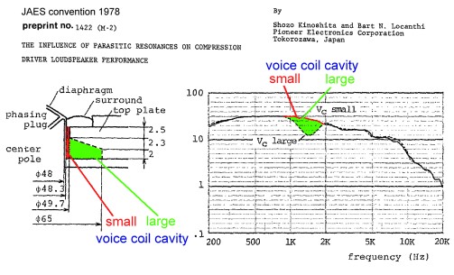
I gave a look twice at the schematics of a part of the compression driver as given in Kinoshita's paper:
http://www.diyaudio.com/forums/atta...2322-jean-michel-lecleach-horns-kinoshita.jpg
What we can see is that the larger voice coil cavity is coupled to
1) the (compression) volume between the dipahragm and the phase plug,
2) a volume on the front of the suround (suspension).
The peak around 1900 is surely related to that coupling.
Best regards from Paris, France
Jean-Michel Le Cléac'h
You'll find in attachment two Hornresp simulations of elctrical impedance obtained for my TD2001 equiavlent model mouted on a Le Cléac'h horn having an Fc =320Hz and T = 0.8.
Vtc = 0,8 cubic centimeter is for the normal volume between the diaphragm and the phase plug (this means a distance around 0.5 millimeter between the diaphragm and the phase plug.
The second curve is for Vtc = 8,10 cubic centimeters. This means that the distance between the diaphragm and thephase plug is 10 times larger now.
We can see that the volume between the diaphragm and the phase plug is responsible for a wide peak centered below 1kHz.
This leads me to conclude that the volume between the diaphragm and the phase plug is not at the origin of the peak at 1900Hz visible on the measured impedance curve of the TD2001 mounted on the Le Cléac'h horn.
Now let's go further:
I gave a look twice at the schematics of a part of the compression driver as given in Kinoshita's paper:
http://www.diyaudio.com/forums/atta...2322-jean-michel-lecleach-horns-kinoshita.jpg
What we can see is that the larger voice coil cavity is coupled to
1) the (compression) volume between the dipahragm and the phase plug,
2) a volume on the front of the suround (suspension).
The peak around 1900 is surely related to that coupling.
Best regards from Paris, France
Jean-Michel Le Cléac'h
I've run a few simus on cavities coupled close to the membrane.
Though I sadly can not demonstrate the effect on the electric impedance –
Might be, I haven't chosen the right volumes and dimensions tho...
Attachments


Hello Michael,
You'll find in attachment two Hornresp simulations of elctrical impedance obtained for my TD2001 equiavlent model mouted on a Le Cléac'h horn having an Fc =320Hz and T = 0.8.
Vtc = 0,8 cubic centimeter is for the normal volume between the diaphragm and the phase plug (this means a distance around 0.5 millimeter between the diaphragm and the phase plug.
The second curve is for Vtc = 8,10 cubic centimeters. This means that the distance between the diaphragm and thephase plug is 10 times larger now.
We can see that the volume between the diaphragm and the phase plug is responsible for a wide peak centered below 1kHz.
This leads me to conclude that the volume between the diaphragm and the phase plug is not at the origin of the peak at 1900Hz visible on the measured impedance curve of the TD2001 mounted on the Le Cléac'h horn.
Now let's go further:
I gave a look twice at the schematics of a part of the compression driver as given in Kinoshita's paper:
http://www.diyaudio.com/forums/atta...2322-jean-michel-lecleach-horns-kinoshita.jpg
What we can see is that the larger voice coil cavity is coupled to
1) the (compression) volume between the dipahragm and the phase plug,
2) a volume on the front of the suround (suspension).
The peak around 1900 is surely related to that coupling.
Best regards from Paris, France
Jean-Michel Le Cléac'h
Thanks Jean-Michel - now anything makes a lot more sense to me (I was just about asking David).
My AxiDriver simu shown so far are not as detailed as yours - its been just a plain diaphragm the size or the throat for now.
So - how you think I best could model that phase plug behaviour - hope I do not need to go into the very details of the phase plug construction (have no drawings anyway)?
Michael
JMLC horns collection.
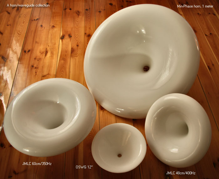
Beautiful background (the wooden floor !) - and foreground too, of course.
A picture of such peaceful harmony we seldom see on that forum - *if* you replace items by proponents 😀 ...

Last edited:
So which do you predict is better will have better performance? Usable bandwidth?😀Hello Michael,
You'll find in attachment two Hornresp simulations of elctrical impedance obtained for my TD2001 equiavlent model mouted on a Le Cléac'h horn having an Fc =320Hz and T = 0.8.
Vtc = 0,8 cubic centimeter is for the normal volume between the diaphragm and the phase plug (this means a distance around 0.5 millimeter between the diaphragm and the phase plug.
The second curve is for Vtc = 8,10 cubic centimeters. This means that the distance between the diaphragm and thephase plug is 10 times larger now.
We can see that the volume between the diaphragm and the phase plug is responsible for a wide peak centered below 1kHz.
This leads me to conclude that the volume between the diaphragm and the phase plug is not at the origin of the peak at 1900Hz visible on the measured impedance curve of the TD2001 mounted on the Le Cléac'h horn.
Now let's go further:
I gave a look twice at the schematics of a part of the compression driver as given in Kinoshita's paper:
http://www.diyaudio.com/forums/atta...2322-jean-michel-lecleach-horns-kinoshita.jpg
What we can see is that the larger voice coil cavity is coupled to
1) the (compression) volume between the dipahragm and the phase plug,
2) a volume on the front of the suround (suspension).
The peak around 1900 is surely related to that coupling.
Best regards from Paris, France
Jean-Michel Le Cléac'h
Hello Soongsc,
Sometimes I have some bad time to understand your questions.
I would says that this one is a silly question as nobody will ever use a compression driver as the TAD TD2001 with a gap from the diaphragm and the phase plug as wide as 5 millimeters!
(the cut-off frequency of the low pass filter equivalent to a compression cavity that large will be low and the bandwith of the driver mounted on the horn very small).
Best regards from Paris, France
Jean-Michel Le Cléac'h
So which do you predict is better will have better performance? Usable bandwidth?😀
Hello Michael,
To model the phase plug can be a very difficult task.
Generally FEM is used.
A starting reference can be:
http://professional.celestion.com/pro/rd/pdfs/AESPAPER.pdf
A bad schematic of the TD2001 is at:
http://audio-heritage.jp/PIONEER-EXCLUSIVE/unit/td-2001(1).JPG
Best regards from Paris, France
Jean-Michel Le Cléac'h
So - how you think I best could model that phase plug behaviour - hope I do not need to go into the very details of the phase plug construction (have no drawings anyway)?
- Home
- Loudspeakers
- Multi-Way
- Jean Michel on LeCleac'h horns