Jean-Michel,Hello Soongsc,
Sometimes I have some bad time to understand your questions.
I would says that this one is a silly question as nobody will ever use a compression driver as the TAD TD2001 with a gap from the diaphragm and the phase plug as wide as 5 millimeters!
(the cut-off frequency of the low pass filter equivalent to a compression cavity that large will be low and the bandwith of the driver mounted on the horn very small).
Best regards from Paris, France
Jean-Michel Le Cléac'h
I am refering to the impedance plots. Which kind of impedance would be deemed to provide better performance? I have experienced how cavity effects can influence direct radiating drivers, so I really don't think it's a silly question. I am curous as to whether there is any experience behind compression driver impedances though. Total area of slits and the location of the slits are also going to effect performance. This will also change the impedance curve shape.
Last edited:
Hello Soongsc,
On a well designed compression drivers the slits inside the phase plug should be considered as a part of the horn. (the throat of which begins at the entrance of the slits)
The total area of the slits (at their input) is for sure very important to consider as the ratio between the area of the diaphragm and the area of the slits (at their input) defines the "compression ratio" of the driver. The compression ratio for compression drivers used in the medium can reach 10 and will be lower for low-mid drivers and even lower (e.g. 2 ) for bass compresssion driver (Goto for instance).
Using such software as Hornresp will enlight you about how the aera of the slits (= area of the throat of the horn), the area of the diaphragm and the volume of the compression cavity influence both the response and the impedance curves.
My best answer to your question about what is the best electric impedance curves is: the smoothest the best.
Best regards from Paris, France.
Jean-Michel Le Cléac'h
Hello Jean-Michel,
I quite agree that well designed compression drivers should be horn specific. However, it seems there is no agreement on what matching criteria is better. I do wonder whether anyone has published research on what the tradeoffs are. It seems that it's impossible to establish a plane wave for over the bandwidth of the driver as many horn designs assume. Additionally, even the compression ratio is not going to be constant simply due to the varying displacement of the diaphragm vs frequency.
I quite agree that well designed compression drivers should be horn specific. However, it seems there is no agreement on what matching criteria is better. I do wonder whether anyone has published research on what the tradeoffs are. It seems that it's impossible to establish a plane wave for over the bandwidth of the driver as many horn designs assume. Additionally, even the compression ratio is not going to be constant simply due to the varying displacement of the diaphragm vs frequency.
Hello Soongsc,
Modelisation and simulation during the design of a compression driver is a stepped procedure.
In a first step we need to design the driver in order to meet the bandwith + efficiency criterions we fixed.
On this step we don't need to uselessly complicate the model.
Then refinment may be done in order to reduce at minimum the detrimental effects of resonances, non linearity, heat, etc.
Then at last we can optimize building details in order to improve, frequency response, distortion, impulse reponse ...
The design of the slits should be one of those very last steps IMHO.
It's a bit twisty, IMHO, to imagine that the displacment of the diaphragm (depending on the frequency) should have an important effect on the compression ratio...
Best regards from Paris, France
Jean-Michel Le Cléac'h
I quite agree that well designed compression drivers should be horn specific. However, it seems there is no agreement on what matching criteria is better. I do wonder whether anyone has published research on what the tradeoffs are. It seems that it's impossible to establish a plane wave for over the bandwidth of the driver as many horn designs assume. Additionally, even the compression ratio is not going to be constant simply due to the varying displacement of the diaphragm vs frequency.
Having only a few years focusing on audio speaker technology, but with probably over 30 years playing around with audio equipment. it seems the same myths have never changed. Are there any significant technology achievements in the audio driver technology that you think made a significant impact on the audio industry? Digging through as much information as I can get my hands on, most of the valuable information seem more than 30 years old. Later advancements seem more market distinguishment and market variation orientated.Hello Soongsc,
Modelisation and simulation during the design of a compression driver is a stepped procedure.
In a first step we need to design the driver in order to meet the bandwith + efficiency criterions we fixed.
On this step we don't need to uselessly complicate the model.
Then refinment may be done in order to reduce at minimum the detrimental effects of resonances, non linearity, heat, etc.
Then at last we can optimize building details in order to improve, frequency response, distortion, impulse reponse ...
The design of the slits should be one of those very last steps IMHO.
It's a bit twisty, IMHO, to imagine that the displacment of the diaphragm (depending on the frequency) should have an important effect on the compression ratio...
Best regards from Paris, France
Jean-Michel Le Cléac'h
About variation of compression ratio. I think more understanding of how the diaphragm vibrates at various frequencies would provide a more clear picture. The Klippel scanner seems like a very valuable tool for this kind of research.
Last edited:
Digging through as much information as I can get my hands on, most of the valuable information seem more than 30 years old.
See? You seem to have hit on something. =)
Actually it would be nice to see if computer modeling and measurements have added anything of real value in the past 30 years.
OT posts deleted

Hello Soongsc,
What are those myths I could have perpetuated?
You are leading this thread outside its initial track. May be you should open a new discussion thread on the design of compression drivers.
Best regards from Paris, France
Jean-Michel Le Cléac'h
it seems the same myths have never changed. Are there any significant technology achievements in the audio driver technology that you think made a significant impact on the audio industry?
What are those myths I could have perpetuated?
You are leading this thread outside its initial track. May be you should open a new discussion thread on the design of compression drivers.
Best regards from Paris, France
Jean-Michel Le Cléac'h
To point out a few myths related with horns/waveguides. Some people swear by horn/waveguides, some totally think they honk. There is no data that clearly identifies the pros and cons that relates with what listeninbg difference we actually can expect. We hear lots of talk about directivity, some people swear by good on-axis response, some swear by contant directivity; again, there is not data that that clearly identifies the pros and cons that relates with what listeninbg difference we actually can expect. It just seems that whichever camp one is in, it's most likely they are in there forever. Whenever someone starts asking questions that experts cannot answer, then the experts get really upset. All this basically has not changed in the past 30 years. This is probably the dominant reason the technology really has not developed much.
Many of these threads start out very good, but once various issues get to a certain level of detail, all hell breaks out and people start taking things personally.
Modeling using BEM/FEM are ways to assist in understanding what's going on. It may never give perfect results, but it surely displays many critical things to take into consideration generally not addressed by lumpsum math models most people are used to. New measurement techniques are also good tools to investigate what actually is going on.
Since how seems at the point where detailed discussion is not possible, I will go sit in the corner until someone says something that I cannot resist responsing to.
You'll find in attachment two Hornresp simulations of elctrical impedance obtained for my TD2001 equiavlent model mouted on a Le Cléac'h horn having an Fc =320Hz and T = 0.8.
Vtc = 0,8 cubic centimeter is for the normal volume between the diaphragm and the phase plug (this means a distance around 0.5 millimeter between the diaphragm and the phase plug.
The second curve is for Vtc = 8,10 cubic centimeters. This means that the distance between the diaphragm and thephase plug is 10 times larger now.
We can see that the volume between the diaphragm and the phase plug is responsible for a wide peak centered below 1kHz.
This leads me to conclude that the volume between the diaphragm and the phase plug is not at the origin of the peak at 1900Hz visible on the measured impedance curve of the TD2001
....
If you allow - I'd like to break down complexity in compression driver design to get a better handle on the subject of band pass effects discussed.
I run a few more sim's to put things into perspective "as good as it gets" 🙂
Below I show what - I think – is equivalent to what's been discussed to be the "band pass behaviour" from the air cushion between diaphragm and phase plug.
What we see there is quite a difference to what's been explained - correct me if I'm wrong.
A rather arbitrary horn contour with an 1" motor attached - specs adjusted to get roughly flat response at the given mic position (mass ~1.5g / compliance ~2.5 E-4m/N) – so its *not* exactly after a particular "real" setup but rather to simplify interpretation of results obtained.
Phase plug / diaphragm distance of ~ 0.5mm :


Phase plug / diaphragm distance of ~ 10mm :


Phase plug / diaphragm distance of ~ 20mm :


Phase plug / diaphragm distance of ~ 30mm


Basically we see the limiting of the pass band being pushed down by increasing the air cushion between membrane and phase plug ...
#########
... Now let's go further:
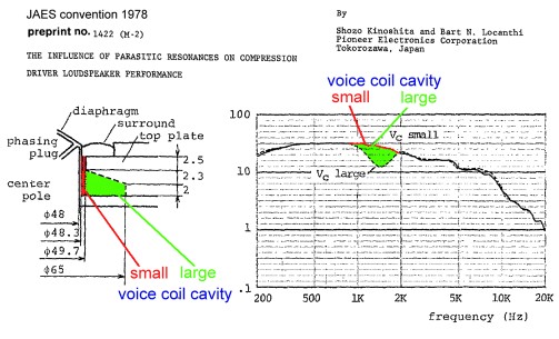
I gave a look twice at the schematics of a part of the compression driver as given in Kinoshita's paper:
http://www.diyaudio.com/forums/atta...2322-jean-michel-lecleach-horns-kinoshita.jpg
What we can see is that the larger voice coil cavity is coupled to
1) the (compression) volume between the dipahragm and the phase plug,
2) a volume on the front of the suround (suspension).
The peak around 1900 is surely related to that coupling.
Jean-Michel - again looking at the picture of Patrick Bateman at
http://www.diyaudio.com/forums/multi-way/103872-geddes-waveguides-76.html#post2049183
I can't see how your point 1) a 2) differ from each other ?
I actually would say that this volume is coupled by on half of the VC gap to the large volume behind the diaphragm and is coupled by the other half of the VC gap to the cushion between the diaphragm and the phase plug.
The latter one acts as an "internal Helmholz resonator" IMO (came as a surprise to me, that such small volumes coupled by such narrow gap does have such impact !):
Again at Phase plug / diaphragm distance of ~ 0.5mm – and in addition - also an "internal Helmholtz resonator" attached to the air cushion between diaphragm and phase plug :


A little bit coarse I admit – but we get the picture I guess
😉
Michael
Last edited:
Probably the volume of helmotz resonator increase the air volume between diaphragm and phase plug, that's why there less performance after the resonance.
Could be - dunno.
The simu isn't *precisely* the situation in the TAD - as there the volume of the Helmholtz resonator is "vented" into the volume behind the membrane by the second half of the VC gap - which is not the case in my simu (too complicated to model for now..).
Michael
The simu isn't *precisely* the situation in the TAD - as there the volume of the Helmholtz resonator is "vented" into the volume behind the membrane by the second half of the VC gap - which is not the case in my simu (too complicated to model for now..).
Michael
Last edited:
Thinking about - for higher frequencies the tiny tunnel to the Helmholtz volume may turn into kinda leakage path - lost energy - hence a drop in SPL ...
Michael
Michael
Michael, I had similar results when side chambers were introduced. As a matter of fact, I did try to use this characteristic to filter breakup modes, but could not get the frequency high enough within the dimensional contrains of the driver.
However, by looking at the pressure distribution in that section of the driver, I did find alternative means to tune the response, but have not formally tested one yet. I think you are doing great.
However, by looking at the pressure distribution in that section of the driver, I did find alternative means to tune the response, but have not formally tested one yet. I think you are doing great.
Last edited:
Thanks Soongsc,
its mostly a "(self-) educative playing around" for me, as I'm not really interested to use compression drivers ( at least as long as I'm happy with the planar's / AMT's on "diffraction alignment device" eg horn's ) nor do I have enough background experience to tell "from scratch"
🙂
Michael
its mostly a "(self-) educative playing around" for me, as I'm not really interested to use compression drivers ( at least as long as I'm happy with the planar's / AMT's on "diffraction alignment device" eg horn's ) nor do I have enough background experience to tell "from scratch"
🙂
Michael
Last edited:
In compression drivers, the VC former is on the same side as the direction of radiation, so this is also a difference from what simulating a normal piston would behave.
One configuration that might worth simulating is using throated phase plug entries instead of flat/parallel to diaphragm.
Hello Michael,
Your simulation demonstrate clearly the low pass filtering due to the compression chamber. Such bandwith / efficiency relation clearly shown in you simulations done at different comrpession chamber volume is (was) commonly used in designing bass horn enclosure (as Klipshorn, ...) .
I attached a figure I modified from Kinoshita. All cavities between diaphragm and throat of the attached horn (not pictured) have been coloured.
The large voice coil cavity is in yellow, the air between the diaphragm and the phase plug is in blue (the air in the slits of the phase plug is also in blue) the air in the coil gap is in purple and the air in the volume between the surround suspension and the body of the driver is in green.
Surely there is similarity with you studied model. The simulation you have done with a lateral cavity linked to the compression champer by a thin duct (this is equivalent to an annular Helmhotz resonator) is of the same kind that the one described by Kinoshita (but the Q of the hole in the frequency response is very different). The important thing is that an optimisation can be done in order to reach a more flat response.
This what Kinoshita wrote:
The main resonances are those due to cavities under the surround and around the voice coil and of the surround itself and the dome. By suppressing or utilizing these resonances, a compression driver having a flat energy response over a wide frequency range is obtainable.
Best regards from Paris, France
Jean-Michel Le Cléac'h
Attachments

Last edited:
The tradeoff of using resonances to obtain banwidth is sound coloration which is visible in the CSD. These techniques are similar whether applied to extend high end or low end of the spectrum. If the extention can be obtained with a very well distributed CSD spectrum, then it will be quite pleasing most of the time.
Hello Soongsc,
What you said is true and I prefer myself to avoid such method.
But in the case it is unavoidable better to have a low Q resonance than a high Q.
Also we have to take in account that it is somewhat possible to compensate a resonance mechanism at the front of the diaphragm by another one at the rear.
An example of such method is called "reactance cancelation" of a horn by a proper choice and calculation of the rear load of the loudspeaker.
Best regards from Paris, France
Jean-Michel Le Cléac'h
The tradeoff of using resonances to obtain banwidth is sound coloration which is visible in the CSD.
.. Your simulation demonstrate clearly the low pass filtering due to the compression chamber. Such bandwith / efficiency relation clearly shown in you simulations done at different comrpession chamber volume is (was) commonly used in designing bass horn enclosure (as Klipshorn, ...) ...
As you mention, I remember having read this in the ancient Klinger booklets. It was described there to be beneficial not to load the bass horn with higher frequencies.
LOL - I've even done a horn project ~25 years back - the so called Smacks bass horn (back loaded) and this one did have such an air cushion (low pass filtering chamber )
An externally hosted image should be here but it was not working when we last tested it.
linked from Thomas Naumann at :
http://speaker-online.de/bauen/naumann/
http://www.speaker-online.de/bauen/naumann/geh.htm
..I attached a figure I modified from Kinoshita. All cavities between diaphragm and throat of the attached horn (not pictured) have been coloured.
...
Surely there is similarity with you studied model.
Pretty complex interactions at a closer look with such compression driver's – eh?
########
You know – my baby is "AMT on horn"
We could look at AMT being sort of compression drivers, with the pleats not squeezing air into small slits of a phase plug - as compression drivers do – but squeezing air out of relatively wide slits (at a slit / bar rate of roughly 1:1).
The equivalence of AMT pleats can be seen IMO in the air cushion between the diaphragm and the phase plug of a compression driver
No voice coil and corresponding Helmholtz cavities to deal with when using AMT. 😉
Also comparing modern AMT design to the slit length of a compression driver – the AMT has fairly short slits
They are somewhere below the wavelength at the upper audio band – and – as my minimalistic experiments indicate – could be made virtually non existent by extending them towards the horn mouth. Looks like a horizontally sectioned horn then 🙂
I think I have to put some more serious investigation into this...
All in all I'm happy to face a way less complicated situation with AMT on horn's.
🙂
🙂
Michael
Michael
Last edited:
- Home
- Loudspeakers
- Multi-Way
- Jean Michel on LeCleac'h horns