Hi I know I can have the boards made and shipped from the pcb manufacturer suggested my miro, but anybody around with a spare set of boards (DAC+PSU) in EU (I guess in Italy it's almost impossible...)? I would really like to try building this dac and hear how can I make it sound with respect to the slightly modded pcm63 dac I currently listen to!
Stefano
Stefano
I apologize Baggerbole, I didn’t realize you were not using the shift registers. If you’re going direct, bypassing shift registers, probably configure it like Ripster mentioned.Yes I sent music trough. I´ve changed the config from #3225 to #618 as Vunce advised.
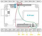
Config is now:
J1-J4 open
B1-B3 closed
B4-B6 open
DR = H3:9
DL = H3:13
BCLK(BCK) = H3:11
LRCK = H3:15
Power connected via USB at H3:17 and H3:19
The scope is new to me. It's like EXCEL or WORD, it can do quite a lot and you use a maximum of 10 percent of it
I don´t have the wire harness for the dig in port.
I have inquired with JLsounds but have not received an answer yet.
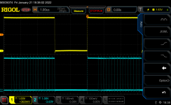
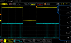
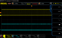
@baggerbole The configuration of #3225 must provide data on DR and DL. Please try it once again and check with probes LRCK+DL and LRCK+DL.
Attachments
I ended up building a whole new DAC and filter PCB to fit discrete op amps.
View here if interested:
https://www.diyaudio.com/community/...est-burson-ada4627-ne5534.381780/post-6916262
View here if interested:
https://www.diyaudio.com/community/...est-burson-ada4627-ne5534.381780/post-6916262
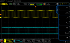
@baggerbole This looks much better, now we have left and right data. What happens now when you connect it to the DAC? 
 ...
... Thanks! Yes good idea from Vunce, and Miro thank you for including part names and orientations on the bottom of the PCB ... very useful
By the way, these DACs still still work if you pull the op amps... Ohm's law and all that. Just in case anyone is curious and wants to know what a simple resistor IV sounds like
By the way, these DACs still still work if you pull the op amps... Ohm's law and all that. Just in case anyone is curious and wants to know what a simple resistor IV sounds like
@miro1360
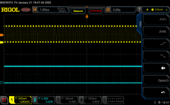
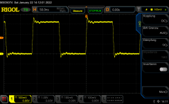
BCK voltage is around 0,4V without DAC connected. Level doesn´t change with DAC connected.
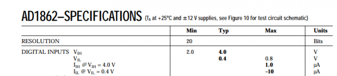
AD1862 spec sheet says we´ll need at least 2v for a "high" on digital inputs...
Supply voltage from smart phone USB to JLsound board is 4,9V
I can hear music on a veeery low level on both chanels superimposed by very loud digital sounds
BCK voltage is around 0,4V without DAC connected. Level doesn´t change with DAC connected.
AD1862 spec sheet says we´ll need at least 2v for a "high" on digital inputs...
Supply voltage from smart phone USB to JLsound board is 4,9V
I can hear music on a veeery low level on both chanels superimposed by very loud digital sounds
Attachments
Last edited:
It's surprisingly difficult to find info about resistor IV's, but I know I've read before about this topology and higher distortion / problems with linearity / etc. The usual concernsInteresting! But looking at the schematic yes I can see the path straight the the IV res.
What does it sound like sans OP?
Why do we even need the OP?!
I was troubleshooting a fresh board last night so I didn't sit down to really listen to the resistor scheme.
I'm also not sure what the feedback cap would do in that arrangement (open a book, asilker) but it would be easy enough to delete it of you were really interested
Edit: the vocabulary is "passive IV", and there is plenty of information for this term. I was not searching correctly before.
Also I owned a Starting Point Systems DAC3 some years ago, which was tda1543 / nos / passive IV and I remember it as sounding smeary and lacking detail. I didn't dislike it, but I also wasn't sad to see it go. FWIW.
Last edited:
@baggerbole Do you have a simple digital multimeter and measure DC voltage on the BCK pin?
And also measure the voltage between H3.17 and H3.19.
And also measure the voltage between H3.17 and H3.19.
Since i connected gnd from JLsound board with gnd from DAC it plays like a charm.
Sometimes it´s so simple - oh boy...
Many thanks to all troubleshooters for their help and patience to a dump DAC newbi - especially Miro.
You´re welcome to my next barbecue
Next homework is a proper supply for I2S board and building a nice home for the boards.
PS: DC Voltage on BCK is 1,67V measured with a multimeter
 GND was not connected?
Yes, stupid me.... pardon for this
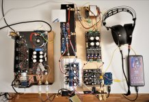
Your AD1862 DAC is WOW
One word describes all!
Very detailed, very dynamic and still absolut musical.
An absolute foot-tapper!
That´s my "windy" test setup
I´m gona make an appropriate home for it.
I am curious if more is possible with tweaking....
To be continued
Your AD1862 DAC is WOW
One word describes all!
Very detailed, very dynamic and still absolut musical.
An absolute foot-tapper!
That´s my "windy" test setup
I´m gona make an appropriate home for it.
I am curious if more is possible with tweaking....
To be continued
Attachments
- Home
- Source & Line
- Digital Line Level
- DAC AD1862: Almost THT, I2S input, NOS, R-2R