Yes there isI am curious if more is possible with tweaking....

I use a TL431 +- shunt regulated design. I got the schematics from the power supply forum here at diyaudio. I dont have access to it for the time being will post the schematic later.
I used the schematic found here https://www.diyaudio.com/community/threads/mini-superreg-for-phono.334946/ You have to scale up the transistors used for the D1, to set the current source at 165ma by using 15R 2W resistors at the Y1 position and to set the voltages at +/- 30V, the resistors at the 2nd half of the TL431 shunt regulator portion at R2, R15 are 10K and for X1 is 910R. I had on hand some BD241 and BD242 from my junk bin, with a continuous collector current of 3 amps which measured a hfe of approximately 176, which I used for the pass transistors. They do run very hot though and adequate heatsinking is a must.I use a TL431 +- shunt regulated design. I got the schematics from the power supply forum here at diyaudio. I dont have access to it for the time being will post the schematic later.
Attachments
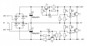
Another schematic you may want to consider is from http://www.garbz.com/electronics-static/projects/dac/ where right at the bottom of the page the psu schematic is given for the D1 i/v. The current source portion is implemented with an LM317 set as current source with about 150ma using a 8R2 resistor. I did not follow this psu schematic because it requires a transformer with 2 secondary windings, which I did not have on hand. I used an EI 50VA 24-0-24 V centre tapped transformer.I used the schematic found here https://www.diyaudio.com/community/threads/mini-superreg-for-phono.334946/ You have to scale up the transistors used for the D1, to set the current source at 165ma by using 15R 2W resistors at the Y1 position and to set the voltages at +/- 30V, the resistors at the 2nd half of the TL431 shunt regulator portion at R2, R15 are 10K and for X1 is 910R. I had on hand some BD241 and BD242 from my junk bin, with a continuous collector current of 3 amps which measured a hfe of approximately 176, which I used for the pass transistors. They do run very hot though and adequate heatsinking is a must.
Attachments
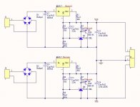
Just for your information, I only used the 1st half of the D1 i/v; without the 2nd half source follower. Nelson Pass himself in posting said, the source follower is unnecessary, if you dont need to run long or highly capacitive cables. The schematic, I used is that posted by stefanobilliani for the TDA1543. https://www.diyaudio.com/community/threads/the-pass-d1-for-tda1543.32999.
Just replace the values R4 with 100K as per the original D1 and if using a single AD1862, R1 is 3K3 and R2 is 6K6. Trim VR1 the source pin of the IRF610 to 0V.
Just replace the values R4 with 100K as per the original D1 and if using a single AD1862, R1 is 3K3 and R2 is 6K6. Trim VR1 the source pin of the IRF610 to 0V.
Attachments
HeyThanks, Markw4, I am new to this, will try out the other option listed in the manual below soon. I am lucky that the board was up and running in no time, so I leave it that way, till now that you mentioned it.
Power I2SoverUSB v.III board:
2. Bus-powered USB side and external power supply for oscillators and reclock.
In this case there is galvanic isolation between the USB side and user
application side. Plug the USB cable to USB B connector, provide external
power supply to H3.17 and H3.19 (4.5V to 5.3V). Consumption from USB host
is less than 400mA, consumption from external power supply for oscillators and
reclock is less than 100mA.
Have you tried the other option?
Just got my second AD1862 DAC operational. The build consists of the not-flipped board, PS2, and LM6171 opamp. I did place 2.7ohm resistors between the DAC and power supply, like I did with my first build. Not sure that I can hear a difference with them in or out.
Next up is the Pedja Rogic's Discrete Diamond Non-Feedback I/V Stage. I built it already and tested the offset without the caps and get 0 mVs in one channel and about 40 mVs in the other. 40 mVs is fairly low, so not sure if I need to install the caps to block the DC.
Anyway I really enjoy this DAC. Thanks miro.
Often times, past wisdom is forgotten due to the passage of time. You guys might want to try out this discrete i/v circuit refined by Rudolf Broertjes. I used to play with this circuit when modding cd payers based on TDA 1541 and PCM63, AD1860, and PCM58 dacs about 20 years ago; and all with very good results. From memory, the sound of the "simple i/v" whilst typically having a BJT signature, unlike FETs or tubes, is engaging and is very good. I recall that op amp based i/v's typically used in cd players when compared against it in shootouts, could not hold a candle to the "simple i/v".
I also recall, that the circuit was initially developed and posted by the late "jocko homo", who had a dry sense of humour and wit, bordering on being irascible. There was much discussion on this and developments therefrom in those early days of diyaudio.
The schematic and instructions for the "simple i/v/" may be found here;
https://www.diyaudio.com/community/threads/simple-i-v-for-tda1541.9226/
If i remember RB made few web pages where were benchmarked few oaps like the LM49990 vs a tube stage on a TDA1541A cd player with close results... is he this guy ?
Yes Jocko Homo loved the AD1862 and really hated you guys ! In the meantime Pedja and Thorsten liked more the TDA1541A.
The latest non feed back transconductance oap legacy of those discussions is the 861 use by Pedja for the Philips chip we talked very soon in this thread. Vunce made a pcb with what Pedja Rogic made public with some input of a member on the buffer stage.
Yes Jocko Homo loved the AD1862 and really hated you guys
! In the meantime Pedja and Thorsten liked more the TDA1541A.The latest non feed back transconductance oap legacy of those discussions is the 861 use by Pedja for the Philips chip we talked very soon in this thread. Vunce made a pcb with what Pedja Rogic made public with some input of a member on the buffer stage.
Can you input of sound difference between both in your whole system, please ?Just got my second AD1862 DAC operational. The build consists of the not-flipped board, PS2, and LM6171 opamp. I did place 2.7ohm resistors between the DAC and power supply, like I did with my first build. Not sure that I can hear a difference with them in or out.
Next up is the Pedja Rogic's Discrete Diamond Non-Feedback I/V Stage. I built it already and tested the offset without the caps and get 0 mVs in one channel and about 40 mVs in the other. 40 mVs is fairly low, so not sure if I need to install the caps to block the DC.
Anyway I really enjoy this DAC. Thanks miro.
Did you sort out the BJT ? From my experience it sounds best w/o DC blocking whatever the caps while some prefer a low end high pass. But even the red non polar Black Gate are less good than no caps imo if not needing DC blocking cap due tio yiur next stage.
- Home
- Source & Line
- Digital Line Level
- DAC AD1862: Almost THT, I2S input, NOS, R-2R